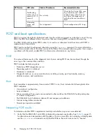
Module status LED patterns
The system and power LED patterns are shown in
Table 15
.
Table 15 Module Status LED patterns during normal operation
LED name
LED color
Status of hardware
Recommended action
No light
Switch is off, boot is not
complete, or boot failed.
Verify that switch is on
and completed booting.
Steady green
Switch is on and
functioning.
No action required.
Flashing green (on 1
second, off 1 second)
One or both of the
following are true:
•
One or more
environmental ranges
are exceeded.
•
Error log contains
one or more port
diagnostic error
messages.
Check environmental
conditions, error log, Port
Status LEDs, transceivers,
cables, and loopback
plugs. Correct error
condition. Clear error
log. Rerun diagnostics to
verify
fi
x.
Module Status
Amber
Boot-up state, one or
more ports of
fl
ine.
Needs attention.
Port link status LED patterns
Table 16
shows the LED color, meaning, and recommended action.
Table 16 Port link status LED patterns
LED name
LED color
Status of hardware
Recommended action
No light
No light or signal carrier
(transceiver or cable) detected.
Check transceiver and cable.
Steady green
Port is online (connected to
external device) but has no traf
fi
c. No action required.
Slow-
fl
ashing
green (on 1
second, off 1
second)
Port is online but segmented,
indicating a loopback cable or
incompatible switch.
Verify that the correct device
is connected to port and that
the switch and port settings are
correct.
Fast-
fl
ashing
green (on 1/2
second, off 1/2
second)
Port is in internal loopback
(diagnostic).
No action required.
Flickering green
Port is online with traf
fi
c
fl
owing
through port.
No action required.
Steady amber
Port is receiving light or signal
carrier, but is not yet online.
No action required.
Slow-
fl
ashing
amber (on 1
second, off 1
second)
Port is disabled as a result of
diagnostics or
portDisable
command. If the LEDs for all
ports are slow-
fl
ashing amber,
the switch could be disabled.
Enable the port using the
portEnable
command; If the
LEDs for all ports are slow-
fl
ashing
amber, enable the switch by
entering the
switchEnable
command.
Port Status
Brocade 8Gb SAN Switch for HP BladeSystem c-Class
35
Summary of Contents for Brocade 8Gb SAN
Page 5: ...Index 61 Brocade 8Gb SAN Switch for HP BladeSystem c Class 5 ...
Page 8: ...8 ...
Page 12: ...12 About this guide ...
Page 18: ...18 Overview ...
Page 40: ...40 Managing the 8Gb SAN Switch ...
Page 46: ...46 Regulatory compliance and safety ...
Page 48: ...48 Electrostatic discharge ...
Page 52: ...52 SAN Switch technical specifications ...
Page 60: ...60 Glossary ...

