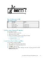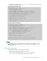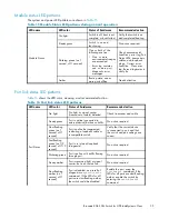
LED name
LED color
Status of hardware
Recommended action
Fast-
fl
ashing
amber (on 1/2
second, off 1/2
second)
Port is faulty.
Check the Port Status LEDs, error
log, transceiver, and cable or
loopback plug. Clear the error
log. Rerun the diagnostics to
verify that the error condition is
fi
xed.
Alternating
green and
amber
Port is bypassed.
Check con
fi
guration of FC loop.
POST and boot speci
fi
cations
POST is a system check that is performed each time the switch is powered on, rebooted, or reset. During
POST, the LEDs
fl
ash different colors. Any errors that occur during POST are listed in the error log.
The 8Gb SAN Switch performs POST when it is turned on or rebooted. Total boot time with POST is
approximately three minutes.
POST can be omitted for subsequent reboots by using the
fastboot
command. For more information
about this command, refer to the latest version of the
Fabric OS command reference guide
. If you suspect
a problem with the switch, enable POST to obtain more information on any failure.
POST
The success/failure results of the diagnostic tests that run during POST can be monitored through the
error log or the command line interface.
POST includes the following steps:
•
Preliminary POST diagnostics are run.
•
Operating system is initialized.
•
Hardware is initialized.
•
Diagnostic tests are run on several functions, including circuitry, port functionality, memory,
statistics counters, and serialization.
Boot
Boot completes in approximately three minutes if POST is run. Boot includes the following tasks after
POST completes:
•
Universal port con
fi
guration
•
Links initialized
•
Fabric is analyzed; if any ports are connected to other switches, the 8Gb SAN Switch participates
in a fabric con
fi
guration
•
The 8Gb SAN Switch obtains a domain ID and assigns port addresses
•
Unicast routing tables constructed
•
Normal port operation enabled
Interpreting POST results
To determine whether POST completed successfully and whether any errors were detected:
1.
Verify that the 8Gb SAN Switch LEDs indicate all components are healthy. See
Table 16
, page 35
for description and interpretation of LED patterns. If one or more LEDs do not display a Healthy state,
use the
switchshow
command to verify that the LEDs on the switch are not set to “beacon”.
36
Managing the 8Gb SAN Switch
Summary of Contents for Brocade 8Gb SAN
Page 5: ...Index 61 Brocade 8Gb SAN Switch for HP BladeSystem c Class 5 ...
Page 8: ...8 ...
Page 12: ...12 About this guide ...
Page 18: ...18 Overview ...
Page 40: ...40 Managing the 8Gb SAN Switch ...
Page 46: ...46 Regulatory compliance and safety ...
Page 48: ...48 Electrostatic discharge ...
Page 52: ...52 SAN Switch technical specifications ...
Page 60: ...60 Glossary ...

