6-43
Removal and Replacement
BAIL ASSEMBLY REMOVAL
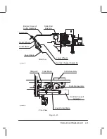
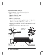
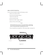
To remove the bail assembly, perform the following procedure:
1. Raise the window and move the pen carriage assembly to the extreme left.
2. Slide the cutter assembly to the extreme right.
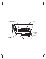
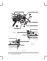
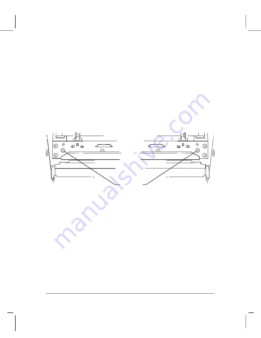
3. Using a TORX T-15 screwdriver, remove the three screws at the left and right ends of
the bail that attach the bail to the left and right bail brackets. See Figure 6-29.
4. Lift the bail up and clear of the plotter.
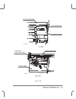
Figure 6-29.
Bail
Screws (3
Each End)
(C)C2858-11
(C)C2858-11
Summary of Contents for C2858A
Page 125: ...7 10 Adjustments Calibrations Notes ...
Page 155: ...9 4 Product History Notes ...
Page 164: ...10 9 Parts and Diagrams Illustrated Parts Breakdown C2859A Electronics Enclosure C C2858 3 1 ...
Page 166: ...10 11 Parts and Diagrams Illustrated Parts Breakdown C2858A Electronics Enclosure C C2858 4 1 ...
Page 182: ...10 27 Parts and Diagrams Illustrated Parts Breakdown Paper Drive Assemblies C C2858 12 1 ...
Page 198: ... ...

