3-13
Installation and Configuration
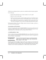
PEN CHECKING
Ink usage for cartridges may vary depending upon the ratio of color versus monochrome
plotting and the extent of each color used. Cartridge replacement is necessary only when any
of the following conditions occur:
Pen Checking is ON and you elect to replace the cartridges when the plotter
prompts you.
Poor plot quality indicates an out of ink condition or the cartridges appear clogged.
When Pen Checking is ON (default), the plotter checks the pens both before and after each
plot for proper electrical contact and nozzle function.
If either of the problems exist, the plotter displays the message “Service pens/Continue”,
You may elect to either ignore the message and continue by pressing the Down Arrow or
select “Service pens” by pressing the Up Arrow button. If you select “Service pens,” the
display tells you whether a pen needs to be replaced (nozzles aren’t working) or reseated
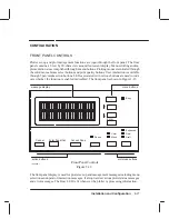
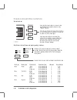
(poor electrical contact). The defective pen position is indicated by a flashing icon in the front
panel display.
When Pen-checking is OFF, the plotter does not check the pens for the above problems; the
only way you’ll be able to tell if you need to replace or reseat a pen is if your print quality is
poor. Use the ink level indicators on the cartridges to check ink levels.
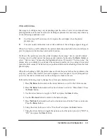
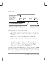
Perform the following steps to change the current pen checking selection.
1. Press
the
Enter button and use the arrow buttons to scroll to the Utilities menu.
2. Press
the
Enter button and use the arrow buttons to scroll to “Menu Mode”. Press
the Enter button.
3. Use the arrow buttons to toggle to “Full” and press the Enter button.
4. Use the Previous button to return to the Status display.
5. Press
the
Enter button and use the arrow buttons to scroll to the Plotter setup menu.
Press the Enter button.
6. Using the arrow buttons, scroll to “Pen check” and press the Enter button.
7. Using the arrow buttons to toggle the options, select the option you want (“OFF” or
“ON”) and press the Enter button.
Summary of Contents for C2858A
Page 125: ...7 10 Adjustments Calibrations Notes ...
Page 155: ...9 4 Product History Notes ...
Page 164: ...10 9 Parts and Diagrams Illustrated Parts Breakdown C2859A Electronics Enclosure C C2858 3 1 ...
Page 166: ...10 11 Parts and Diagrams Illustrated Parts Breakdown C2858A Electronics Enclosure C C2858 4 1 ...
Page 182: ...10 27 Parts and Diagrams Illustrated Parts Breakdown Paper Drive Assemblies C C2858 12 1 ...
Page 198: ... ...

