background image

HP Part Number 5990-3463, Doc # 5990-3463-1


Revised July 2002

HP Surestore Drive Rail Mounting Kit

This document includes steps to install drive rails on HP Surestore internal tape drives for installation in HP Servers. The
drive rail mounting kit includes two sets of drive rails and the hardware to install the drive rails on the tape drives.

Drive Rail Selection

The drive rail mounting kit includes a set of plastic drive rails (

Figure 2

) and metal drive rails (

Figure 5

) to attach the

rails to the HP Surestore tape drive.

Plastic drive rails are always used in mounting the DAT 24i and DAT 40i drives in the HP Servers.

Metal drive rails are used in mounting all other drives in the HP Servers.

The kit also includes screw sub-kits for mounting the metal drive rails to the HP Surestore tape drive. See

Table 3.

for

the screw sub-kits and mounting slot appropriate for each HP Surestore tape drive.

Tools Required (Metal Drive Rails Only)

The following tools are required to install the metal drive rails:

T-10 TORX

®

screwdriver

Number 1 Phillips

®

screwdriver

Posidrive

®

screwdriver

Where to Obtain Additional Installation Instructions

Complete mass storage device installation instructions can be found in both of the following sources:

The HP Server Operations and Maintenance Guide, on the HP Server Documentation CD-ROM shipped with your
HP server, has a complete chapter on installation.

The HP Server Operations and Maintenance Guide for your HP Server can be viewed and printed from the official
HP web site:

http://www.hp.com

Refer to the web site for the latest revisions and product updates.

Configuration Guidelines

HP Server tc3100 Configuration

The HP Server tc3100 can accept either of the following HP Surestore tape drives:

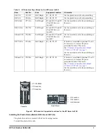
Table 1. HP Surestore Tape Drives for the HP Server tc3100

Drive

Part No.

Size

Supported Location

Comments

DAT 24i

C1555D

Half Height

P2, R2

Use the plastic drive rails when installing the
drive on the tc3100 server.

DAT 40i

C5686A

Half Height

P2, R2

Use the plastic drive rails when installing the
drive on the tc3100 server.

Summary of Contents for C5687A - SureStore DAT 40i Tape Drive

Page 1: ...Rails Only The following tools are required to install the metal drive rails T 10 TORX screwdriver Number 1 Phillips screwdriver Posidrive screwdriver Where to Obtain Additional Installation Instructions Complete mass storage device installation instructions can be found in both of the following sources The HP Server Operations and Maintenance Guide on the HP Server Documentation CD ROM shipped wi...

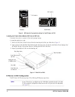
Page 2: ...seated against the side of the drive 3 Repeat the installation for the second mounting rail Figure 2 Plastic Drive Rails HP Server tc4100 Configuration The HP Server tc4100 can accept any of the following HP Surestore tape drives Figure 1 HP Surestore Supported Locations for the HP Server tc3100 NOTE In any of these server configurations the CD ROM is normally mounted in location P1 in the pedesta...

Page 3: ...ils when installing on the server Ultrium 230i C7400A Full Height R1 and R2 P2 and P3 Two HH slots are required Use the metal drive rails when installing on the server DLT VS80i C7504A Half Height R1 R2 P2 P3 If this drive is installed in position P2 or P3 it is necessary to remove the power protection bracket of the server See Clearance Considerations Model C7504A or C7420A on page 5 Use the meta...

Page 4: ...drive screw holes 2 Secure the drive rail with the appropriate screws for the tape drive see Table 3 3 Repeat the installation for the second drive rail 4 Insert the tape drive into the server and secure with chassis screws Q1497 60008 NOTE Do not over torque the mounting screws Too much torque can damage the threading on the rails Table 3 Metal Drive Rail Mounting Slot and Screw Specification Dri...

Page 5: ... installing the C7504A or C7420A tape drive refer to your HP Server Operations and Maintenance Guide to power down and open the server To remove the power protection bracket 1 If the server is operating log off all users back up files and power down the server 2 Disconnect the power cord and any external cables connected to the server If necessary label each one to expedite re assembly 3 Open the ...

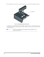
Page 6: ...at the rear of the non hot swap cage see Figure 7 Undo the captive Torx screw securing the power protection bracket to the power distribution assembly Remove the power protection bracket and screw from the server Figure 6 Removing the System Fan Assembly NOTE The power protection bracket and screw should be saved for reinstallation if the tape drive is later removed Thumbscrew ...

Page 7: ...external cables and power cord 9 Power up the server and return it to normal operation Figure 7 Removing the Power Protection Bracket Bracket is accessible from this position Captive Screw Power Protection Bracket Power Distribution Assembly NOTE It is not necessary to remove the Power Distribution Assembly from the chassis in order to remove the Power Protection Bracket This view is used to indic...

Page 8: ...axes provide telephone assistance on replacement of the component and pay shipping charges duty and taxes for any part that HP asks to be returned The customer may be required to run HP supplied configuration and diagnostic programs before a replacement will be dispatched or an on site visit is authorized Refer to the warranty statement provided with your original HP Server system documentation fo...

Reviews: