7Ć3
Calibrations
C3187Ć90000
FrontĆPanel Keys in Service Mode
Pressingany single frontĆpanel key in service mode performs the same operation as in
normal mode. However, in service mode, you can also use combinations of keys, to perform
the various service tests and calibrations. With this intent, the
Replot
key acts as a
SHIFT
key,
and the
Cancel
key acts as an
ALT
key.
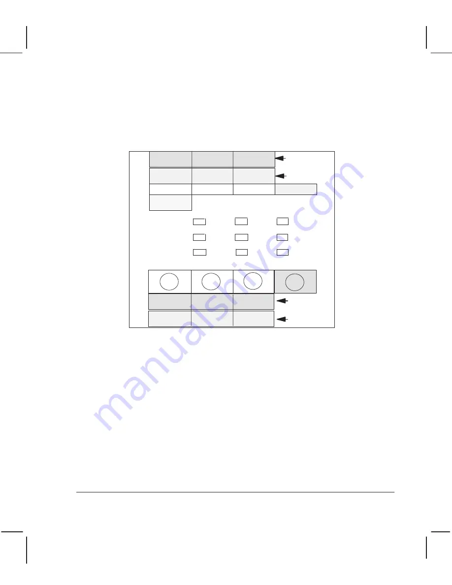
The followingillustration indicates which service tests and calibrations are assigned to which
frontĆpanel keys. A frontĆpanel overlay is provided with this manual; you can place it over
the actual keys on the plotter. The designation of keys for service tests is also shown on the
service configuration plot.
Service
Configuration
Electrical
Test
Accuracy
Calib. Print
Accuracy
Calib. Read
Input/Output
Test
Stepper
Motor Test
Bail Sensor
Test
Bail Cycle
Test
Bail
Calibration
Servo/Encoder
Test
Setup-Sheet
Calibration
Media-Sensor
Calibration
Service Monitor
with Shift + Alt
To check whether a DesignJet 220 plotter is in service mode, press the
ALT
and
SHIFT
keys
together, and then release them. If the plotter is in service mode, four LEDs
Draft, Final, Paper
and
Transl/Vellum
flash. Press any key and they stop flashing.
Performing Tests and Calibrations
The general procedure to perform a service test or calibration is as follows:
,
Once in service mode (see previous page), hold down the
SHIFT
or
ALT
key, whichever is
appropriate for the service test you want to perform.
.
Without releasingthe
SHIFT
or
ALT
key, press the key correspondingto the service test or
calibration you want to perform.
A
Release the keys once the
Busy
LED lights up.
Procedures specific to each calibration are given on the following pages.
(Service tests
chapter 8.)
Summary of Contents for CalcPad 200
Page 1: ... ...
Page 3: ... ...
Page 14: ... ...
Page 15: ... ...
Page 19: ... ...
Page 22: ...2Ć4 Site Planning and Requirements C3187Ć90000 ...
Page 23: ... ...
Page 27: ... 4 1 2 3 4 5 6 mm 0 25 in 5 1 2 3 4 5 B A B A A B A B X X X ...
Page 31: ... ...
Page 33: ... ...
Page 65: ... ...
Page 139: ... ...
Page 149: ...8Ć0 8 Troubleshooting ...
Page 178: ...8Ć30 Removal and Replacement C3187Ć90000 ...
Page 179: ...9Ć0 9 Product History and Service Notes ...
Page 193: ...10Ć1 10 Parts and Diagrams ...
Page 197: ...10Ć5 Parts and Diagrams C3187Ć90000 Legs and Media Bin 1 2 3 3 4 5 6 7 1 3 4 3 3 3 3 3 8 8 ...
Page 199: ...10Ć7 Parts and Diagrams C3187Ć90000 Window Center and Bottom Covers To Carriage ...
Page 203: ...10Ć11 Parts and Diagrams C3187Ć90000 Left Endcover and Trim ...
Page 205: ...10Ć13 Parts and Diagrams C3187Ć90000 Right Endcover and Trim ...
Page 207: ...10Ć15 Parts and Diagrams C3187Ć90000 Carriage Axis Drive Left End ...
Page 209: ...10Ć17 Parts and Diagrams C3187Ć90000 Service Station 1 2 3 3 4 5 7 6 6 ...
Page 215: ...10Ć23 Parts and Diagrams C3187Ć90000 Media Drive Assemblies ...
Page 219: ...10Ć25 Parts and Diagrams C3187Ć90000 Bail and Overdrive Assemblies ...
Page 221: ...10Ć27 Parts and Diagrams C3187Ć90000 Pinch Arm Assembly ...
Page 227: ... ...
Page 231: ... ...
Page 244: ...IndexĆ04 C3087Ć90000 ...
Page 245: ... ...


