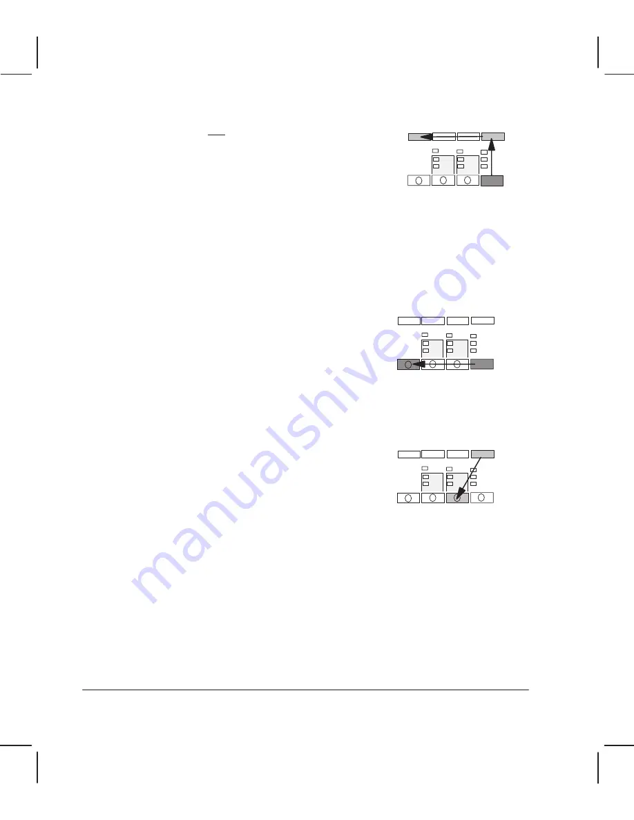
SHIFT
Service
Monitor
ALT
ALT
Servo/Encoder Test
SHIFT
Stepper
Motor Test
8Ć24 Removal and Replacement
C3187Ć90000
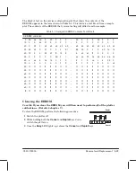
Service Monitor (Data Display)
1
Enter service mode (see page 7Ć2).
2
Hold down the
SHIFT
and
ALT
keys and press
Service Monitor
.
3
Send the file or files from the computer through the serial
or parallel ports.
4
Press any frontĆpanel key when the file(s) have been
transferred to the plotter.
5
Load a sheet of media (A3 size or B size minimum) in portrait orientation.
Instead of plotting the drawings that you sent, the plotter plots the first and last
Kbytes of the code for those drawings. The code is printed in hexadecimal and ASCII
format. If the total size of the files sent is not bigger than one Kbyte, only the first
buffer is printed. The plotter exits the service monitor mode if the files sent contain
PJL universal exit language.
6
Compare the code printed with the code sent from the computer to check if
communication between the computer and the plotter is functioning correctly.
Servo/Encoder Test
1
Enter service mode (see page 7Ć2).
2
Hold down the
ALT
key and press
Servo/Encoder Test
.
The
LED lights upand the carriage moves to the center of the plotter. Both the
carriage and the roller then move backwards and forwards in cycles of six short steps,
changing direction between cycles.
3
Press any frontĆpanel key to stop the test.
StepperĆMotor Test
1
Enter service mode (see page 7Ć2).
2
Hold down the
SHIFT
key and press
Stepper Motor Test
.
The
Busy
LED lights up and the stepper motor switches on, continuously raising and
lowering the wiper and the lever mechanism.
3
Press the
ALT
key when you want to stop the test.
WindowĆSensor Test
1
With the
Load Media
LED lit, open the window.
The
Ready
LED should flash.
2
Close the window again.
The
Ready
LED should stopflashing, and the
Load Media
LED should light upagain.
Summary of Contents for CalcPad 200
Page 1: ... ...
Page 3: ... ...
Page 14: ... ...
Page 15: ... ...
Page 19: ... ...
Page 22: ...2Ć4 Site Planning and Requirements C3187Ć90000 ...
Page 23: ... ...
Page 27: ... 4 1 2 3 4 5 6 mm 0 25 in 5 1 2 3 4 5 B A B A A B A B X X X ...
Page 31: ... ...
Page 33: ... ...
Page 65: ... ...
Page 139: ... ...
Page 149: ...8Ć0 8 Troubleshooting ...
Page 178: ...8Ć30 Removal and Replacement C3187Ć90000 ...
Page 179: ...9Ć0 9 Product History and Service Notes ...
Page 193: ...10Ć1 10 Parts and Diagrams ...
Page 197: ...10Ć5 Parts and Diagrams C3187Ć90000 Legs and Media Bin 1 2 3 3 4 5 6 7 1 3 4 3 3 3 3 3 8 8 ...
Page 199: ...10Ć7 Parts and Diagrams C3187Ć90000 Window Center and Bottom Covers To Carriage ...
Page 203: ...10Ć11 Parts and Diagrams C3187Ć90000 Left Endcover and Trim ...
Page 205: ...10Ć13 Parts and Diagrams C3187Ć90000 Right Endcover and Trim ...
Page 207: ...10Ć15 Parts and Diagrams C3187Ć90000 Carriage Axis Drive Left End ...
Page 209: ...10Ć17 Parts and Diagrams C3187Ć90000 Service Station 1 2 3 3 4 5 7 6 6 ...
Page 215: ...10Ć23 Parts and Diagrams C3187Ć90000 Media Drive Assemblies ...
Page 219: ...10Ć25 Parts and Diagrams C3187Ć90000 Bail and Overdrive Assemblies ...
Page 221: ...10Ć27 Parts and Diagrams C3187Ć90000 Pinch Arm Assembly ...
Page 227: ... ...
Page 231: ... ...
Page 244: ...IndexĆ04 C3087Ć90000 ...
Page 245: ... ...


