8Ć26 Removal and Replacement
C3187Ć90000
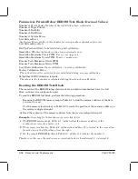
Parameters Printed Below EEROM Text Block
(Decimal Values)
Number of Power Cycles
Number of times plotter has been switched on.
Number of Pages Printed
Number of Bail Lifts
Number of Bail Errors
Number of System Errors
Last System Error
See System Errors earlier in this chapter for correspondence of numbers to errors.
Last System Error Data
Bail Up Position Offset
Calculated during bail calibration.
Bench Run
Whether the bench run has been performed or not.
Bench Run Maximum YĆAxis PWM
YĆaxis = carriage axis.
Bench Run Maximum XĆAxis PWM
XĆaxis = media axis.
Encoder Tests Maximum YĆAxis PWM
Encoder Tests Maximum XĆAxis PWM
Last XĆAxis Calibration
XĆaxis calibration = accuracy calibration
Factory Calibration Factor
This is the driveĆroller correction factor, calculated during accuracy calibration.
Setup Sheet LED Calibration formula.
The values in the formula are calculated during the setupĆsheet calibration.
Reading the EEROM Text Block
The contents of the EEROM integrated circuit are printed in hexadecimal form in a text
block on the service configuration plot.
To read the EEROM text block, perform the following procedure:
,
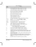
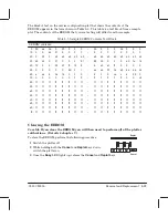
Examine the EEROM memory map in Table 8Ć1 to find the memory address of the data
you want to read.
.
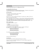
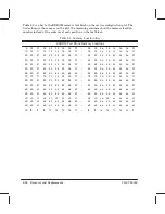
Use the memory location key in Table 8Ć2 to locate the position of the memory address on
the service configuration plot.
A
Read the contents of the memory address from the service configuration plot.
Example:
Searching for the mediaĆsensor correction factor
1
The EEROM memory map Table 8Ć1 indicates that the memory address of the
mediaĆsensor correction factor is 1b.
2
The memory location key Table 8Ć2 indicates that address 1b is located in the second row
from the top, in the fifth column from the right.
3
On the sample EEROM text blockTable 8Ć3, address 1b contains the number 0.
Therefore, in this case, the mediaĆsensor correction factor is hexadecimal 0 = decimal 0.
Summary of Contents for CalcPad 200
Page 1: ... ...
Page 3: ... ...
Page 14: ... ...
Page 15: ... ...
Page 19: ... ...
Page 22: ...2Ć4 Site Planning and Requirements C3187Ć90000 ...
Page 23: ... ...
Page 27: ... 4 1 2 3 4 5 6 mm 0 25 in 5 1 2 3 4 5 B A B A A B A B X X X ...
Page 31: ... ...
Page 33: ... ...
Page 65: ... ...
Page 139: ... ...
Page 149: ...8Ć0 8 Troubleshooting ...
Page 178: ...8Ć30 Removal and Replacement C3187Ć90000 ...
Page 179: ...9Ć0 9 Product History and Service Notes ...
Page 193: ...10Ć1 10 Parts and Diagrams ...
Page 197: ...10Ć5 Parts and Diagrams C3187Ć90000 Legs and Media Bin 1 2 3 3 4 5 6 7 1 3 4 3 3 3 3 3 8 8 ...
Page 199: ...10Ć7 Parts and Diagrams C3187Ć90000 Window Center and Bottom Covers To Carriage ...
Page 203: ...10Ć11 Parts and Diagrams C3187Ć90000 Left Endcover and Trim ...
Page 205: ...10Ć13 Parts and Diagrams C3187Ć90000 Right Endcover and Trim ...
Page 207: ...10Ć15 Parts and Diagrams C3187Ć90000 Carriage Axis Drive Left End ...
Page 209: ...10Ć17 Parts and Diagrams C3187Ć90000 Service Station 1 2 3 3 4 5 7 6 6 ...
Page 215: ...10Ć23 Parts and Diagrams C3187Ć90000 Media Drive Assemblies ...
Page 219: ...10Ć25 Parts and Diagrams C3187Ć90000 Bail and Overdrive Assemblies ...
Page 221: ...10Ć27 Parts and Diagrams C3187Ć90000 Pinch Arm Assembly ...
Page 227: ... ...
Page 231: ... ...
Page 244: ...IndexĆ04 C3087Ć90000 ...
Page 245: ... ...


