1.
Prepare the computer for disassembly (
Preparation for disassembly on page 26
2.
Remove the bottom cover (
).
3.
Disconnect the battery cable from the system board (see
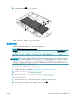
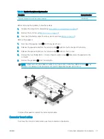
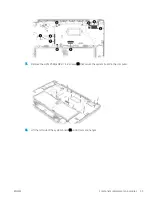
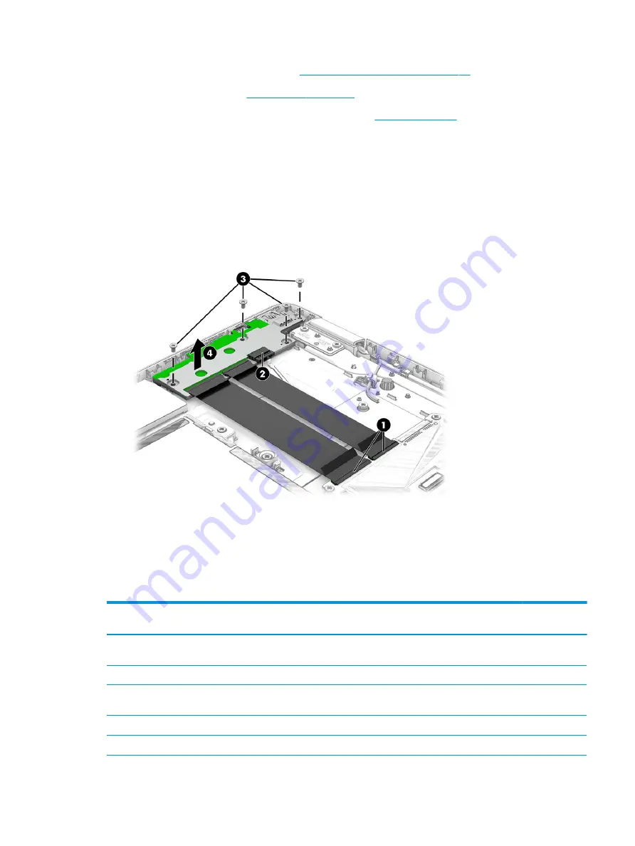
Remove the connector board:
1.
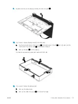
Release the ZIF connectors (1) to which the connector board cables are connected, and then disconnect the
cables from the system board.
2.
Disconnect the power cable (2) from the connector board.
3.
Remove the four Phillips M2.0 × 4.2 screws (3) that secure the connector board to the computer.
4.
Remove the connector board (4) from the computer.
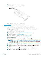
To replace the connector board, reverse the removal procedures.
System board
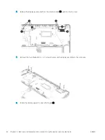
To remove the system board, use these procedures and illustrations.
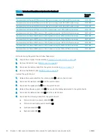
Table 5-6
System board descriptions and part numbers
Description
Spare part
number
NOTE:
All system board spare part kits include an integrated processor, a graphics subsystem with UMA memory, and replacement
thermal material. Replacement thermal material is also available in the Thermal Pad Kit, spare part number M15302-001.
Equipped with an Intel Pentium Silver N5030 processor, 4 GB of system memory, and 128 GB of eMMC system storage
M15316-001
Equipped with an Intel Pentium Silver N5030 processor, 8 GB of system memory, 64 GB of eMMC system storage, and
fBLAR
M24577-001
Equipped with an Intel Pentium Silver N5030 processor, 8 GB of system memory, and 64 GB of eMMC system storage
M15317-001
Equipped with an Intel Pentium Silver N5030 processor, 4 GB of system memory, and 32 GB of eMMC system storage
M15315-001
ENWW
Component replacement procedures
33
Summary of Contents for Chromebook x360 14a
Page 4: ...iv Safety warning notice ENWW ...
Page 30: ...24 Chapter 4 Removal and replacement procedures preliminary requirements ENWW ...
Page 57: ...ENWW Erase and reformat the recovery media 51 ...
Page 58: ...52 Chapter 6 Backing up resetting and recovering ENWW ...
Page 62: ...56 Chapter 7 Specifications ENWW ...
Page 66: ...60 Chapter 8 Power cord set requirements ENWW ...
Page 68: ...62 Chapter 9 Recycling ENWW ...


