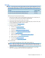
System board
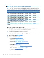
NOTE:
All system board spare part kits include the ExpressCard assembly.
NOTE:
All system board spare part kits include replacement thermal material. Replacement thermal
material is also available in the Thermal Material Kit, spare part numbers 413706-001 (for use only in
the United States) and 445853-001 (for use only in Japan and Asia Pacific countries and regions).
Description
Spare part number
For use only with computer models equipped with Intel Core 2 Duo processors and discrete
graphics subsystem (includes 128-MB DDR2 discrete graphics system memory)
456613-001
For use only with computer models equipped with Intel Core 2 Duo processors and discrete
graphics subsystem (includes 64-MB DDR2 discrete graphics system memory)
456612-001
For use only with computer models equipped with Intel Core 2 Duo processors and discrete
graphics subsystem (includes 128-MB DDR1 discrete graphics system memory)
456611-001
For use only with computer models equipped with Intel Core 2 Duo processors and discrete
graphics subsystem (includes 64-MB DDR1 discrete graphics system memory)
456610-001
For use only with computer models equipped with Intel Core 2 Duo processors and UMA graphics
subsystem
456608-001
For use only with computer models equipped with Intel Celeron M processors and UMA graphics
subsystem
456609-001
Before removing the system board, follow these steps:
1.
Shut down the computer. If you are unsure whether the computer is off or in Hibernation, turn
the computer on, and then shut it down through the operating system.
2.
Disconnect all external devices connected to the computer.
3.
Disconnect the power from the computer by first unplugging the power cord from the AC outlet
and then unplugging the AC adapter from the computer.
4.
Remove the battery (see
Battery on page 37
).
5.
Remove the following components:
a.
Hard drive (see
Hard drive on page 38
)
b.
Optical drive (see
Optical drive on page 45
)
c.
Keyboard (see
Switch cover and keyboard on page 47
)
d.
Switch cover (see
Switch cover and keyboard on page 47
)
e.
Speaker (see
Speaker on page 51
)
f.
Display lid switch module (see
Display lid switch module on page 52
)
g.
Display assembly (see
Display assembly on page 53
)
h.
Top cover (see
Top cover on page 58
)
66
Chapter 4 Removal and replacement procedures
Summary of Contents for Compaq 6520s
Page 1: ...HP Compaq 6520s Notebook PC Maintenance and Service Guide ...
Page 4: ...iv MSG revision history ...
Page 6: ...vi Safety warning notice ...
Page 24: ...Computer major components 14 Chapter 3 Illustrated parts catalog ...
Page 113: ...Where used 2 screws that secure the top cover to the base enclosure Torx T8M2 5 7 0 screw 103 ...
Page 141: ...RJ 11 modem Pin Signal 1 Unused 2 Tip 3 Ring 4 Unused 5 Unused 6 Unused RJ 11 modem 131 ...

