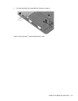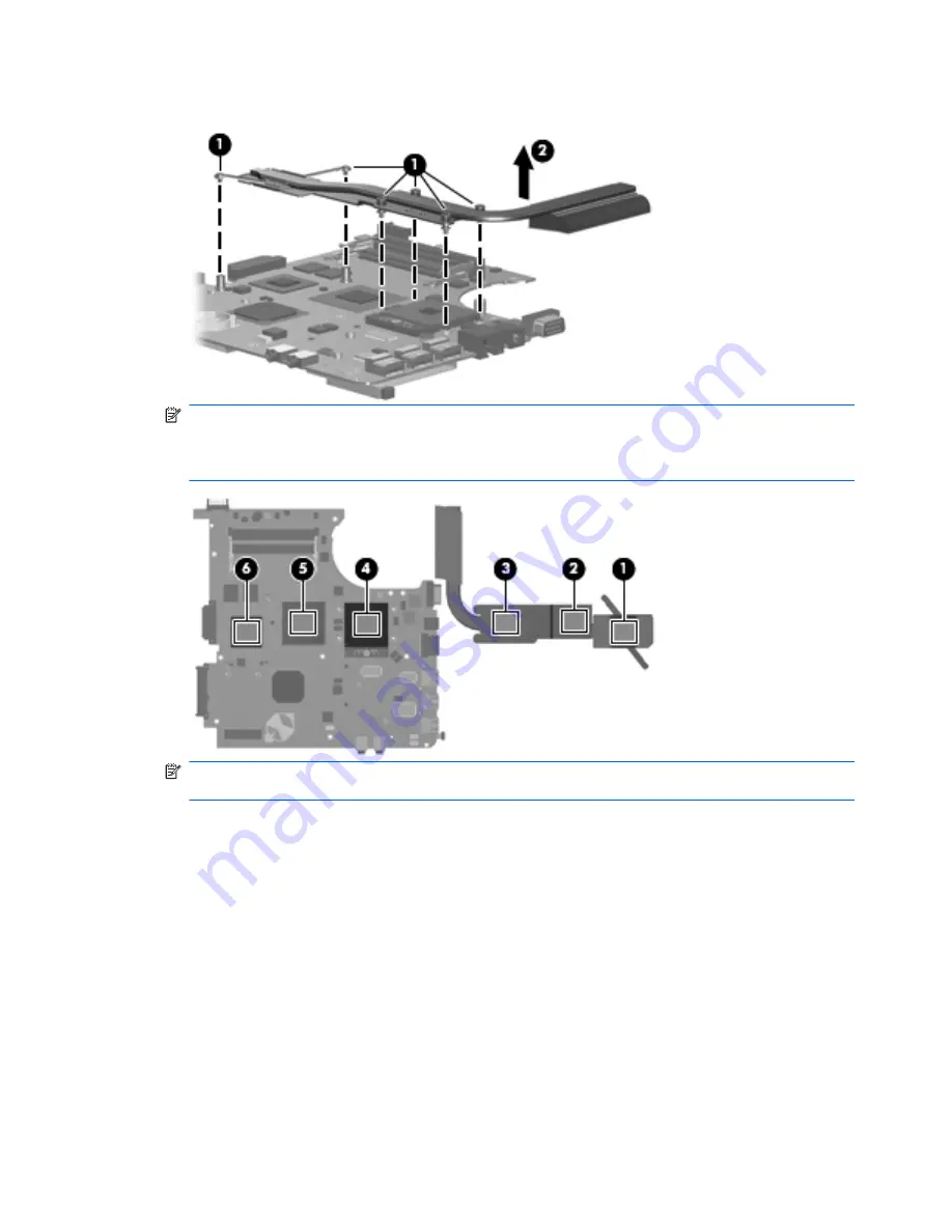
3.
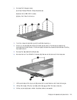
Remove the heat sink
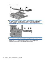
(2)
.
NOTE:
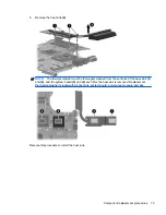
The thermal material must be thoroughly cleaned from the surfaces of the heat sink
(1)
,
(2)
, and
(3)
, and the system board components
(4)
,
(5)
, and
(6)
each time the heat sink is
removed. Replacement thermal material is included with all heat sink, system board, and
processor spare part kits.
NOTE:
Steps 4 and 5 apply only to computer models equipped with graphics subsystems with
UMA memory.
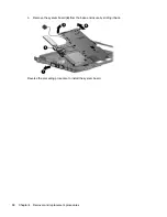
4.
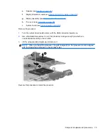
Following the 1, 2, 3, 4, sequence stamped into the heat sink, loosen the four Phillips
PM2.5×10.0 screws
(1)
that secure the heat sink to the system board.
72
Chapter 4 Removal and replacement procedures
Summary of Contents for Compaq 6520s
Page 1: ...HP Compaq 6520s Notebook PC Maintenance and Service Guide ...
Page 4: ...iv MSG revision history ...
Page 6: ...vi Safety warning notice ...
Page 24: ...Computer major components 14 Chapter 3 Illustrated parts catalog ...
Page 113: ...Where used 2 screws that secure the top cover to the base enclosure Torx T8M2 5 7 0 screw 103 ...
Page 141: ...RJ 11 modem Pin Signal 1 Unused 2 Tip 3 Ring 4 Unused 5 Unused 6 Unused RJ 11 modem 131 ...

