

Hardware Reference Guide
www.hp.com
Index-1
Index
3.5-inch drive bay
2–30
3.5-inch hard drive
upgrading
2–25
A
access panel, removing
2–4
,
2–6
application key
1–4
arrow keys
1–4
audio connector
1–3
B
battery
coin cell (type 1)
C–2
coin cell (type 2)
C–3
battery replacement
C–1
bezel
2–32
bezel blank, removing
2–32
C
cable lock installation
D–1
cables
optical drive
2–24
coin cell battery
type 1
C–2
type 2
C–3
components
front panel
1–2
keyboard
1–4
rear panel
1–3
computer care guidelines
G–1
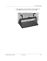
computer stand
2–5
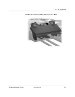
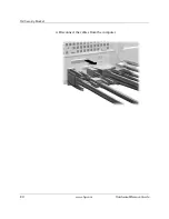
connecting cables
2–24
CTRL key
1–4
D
DDR-SDRAM
2–8
desktop drive positions
2–19
DIMMs
2–8
DIMMs (dual inline memory modules)
installing
2–11
,
2–13
diskette drive
activity light
1–2
eject button
1–2
removing
2–21
drive bay
2–11
drive installation guidelines
2–18
E
Easy Access buttons
1–4
Easy Access drive bay
removing
2–25
rotating
2–11
easy access keyboard
components
1–4
customizing
1–5
editing keys
1–4
electrostatic discharge
2–1
,
F–1
expansion card, installing
2–14
,
2–16
expansion slot cover, removing
2–15
F
FailSafe key
2–2
front bezel, removing
2–4
,
2–7
front panel components
1–2
Summary of Contents for Compaq d330 ST
Page 46: ...2 36 www hp com Hardware Reference Guide Hardware Upgrades ...
Page 56: ...D 2 www hp com Hardware Reference Guide Security Lock Provisions I Installing a Padlock ...
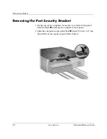
Page 66: ...E 10 www hp com Hardware Reference Guide Port Security Bracket ...
Page 72: ...G 4 www hp com Hardware Reference Guide Routine Computer Care and Shipping Preparation ...


