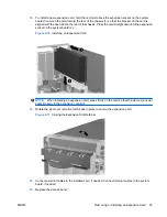
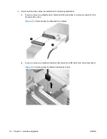
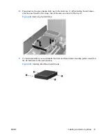

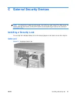
3.
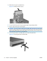
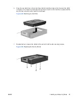
Position the guide screws on the drive into the J-slots in the drive bay. Then slide the drive toward
the front of the computer until it locks into place.
Figure 2-34
Installing a Drive into the 3.5-inch Drive Bay (Diskette Drive shown)
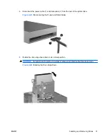
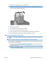
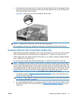
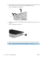
4.
Connect the appropriate drive cables:
a.
If installing a diskette drive, connect the power and data cables to the rear of the drive and
connect the other end of the data cable to the connector on the system board labeled FLOPPY.
b.
If installing a second hard drive, connect the power and data cables to the rear of the drive
and connect the other end of the data cable to the next available (unpopulated) SATA
connector on the system board in the following order: SATA0, SATA1, SATA5, SATA4.
c.
If installing a media card reader, connect the USB cable from the media card reader to the
USB connector on the system board labeled MEDIA.
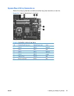
NOTE:
Refer to
System Board Drive Connections on page 29
for an illustration of the system
board drive connectors.
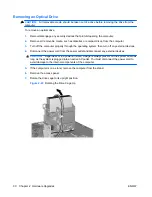
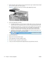
5.
Replace the optical drive.
6.
Replace the front bezel and access panel.
7.
If the computer was on a stand, replace the stand.
8.
Reconnect the power cord and turn on the computer.
9.
Lock any security devices that were disengaged when the access panel was removed.
38
Chapter 2 Hardware Upgrades
ENWW
Summary of Contents for Compaq dc5800
Page 1: ...Hardware Reference Guide dc5800 Small Form Factor Model HP Compaq Business PC ...
Page 4: ...iv About This Book ENWW ...
Page 14: ...8 Chapter 1 Product Features ENWW ...
Page 58: ...52 Appendix B Battery Replacement ENWW ...
Page 60: ...Padlock Figure C 2 Installing a Padlock 54 Appendix C External Security Devices ENWW ...
Page 64: ...58 Appendix C External Security Devices ENWW ...


