background image

Computer Setup (F10) Utility Guide

www.hp.com

iii

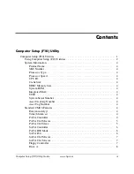
Contents

Computer Setup (F10) Utility

Computer Setup (F10) Utilities . . . . . . . . . . . . . . . . . . . . . . . . . . . . . . . . . . . . . . . . . . . . .   1

Using Computer Setup (F10) Utilities  . . . . . . . . . . . . . . . . . . . . . . . . . . . . . . . . . . . .   2
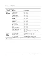
System Information. . . . . . . . . . . . . . . . . . . . . . . . . . . . . . . . . . . . . . . . . . . . . . . . . . .   4

Product Name . . . . . . . . . . . . . . . . . . . . . . . . . . . . . . . . . . . . . . . . . . . . . . . . . . . .   4
SKU Number . . . . . . . . . . . . . . . . . . . . . . . . . . . . . . . . . . . . . . . . . . . . . . . . . . . .   4
Processor Type . . . . . . . . . . . . . . . . . . . . . . . . . . . . . . . . . . . . . . . . . . . . . . . . . . .   4
Processor Speed . . . . . . . . . . . . . . . . . . . . . . . . . . . . . . . . . . . . . . . . . . . . . . . . . .   4
CPU ID . . . . . . . . . . . . . . . . . . . . . . . . . . . . . . . . . . . . . . . . . . . . . . . . . . . . . . . . .   4
Cache Size  . . . . . . . . . . . . . . . . . . . . . . . . . . . . . . . . . . . . . . . . . . . . . . . . . . . . . .   4
DDR2 Memory Size. . . . . . . . . . . . . . . . . . . . . . . . . . . . . . . . . . . . . . . . . . . . . . .   4
System ROM  . . . . . . . . . . . . . . . . . . . . . . . . . . . . . . . . . . . . . . . . . . . . . . . . . . . .   4
Integrated MAC . . . . . . . . . . . . . . . . . . . . . . . . . . . . . . . . . . . . . . . . . . . . . . . . . .   4
UUID  . . . . . . . . . . . . . . . . . . . . . . . . . . . . . . . . . . . . . . . . . . . . . . . . . . . . . . . . . .   4
System Serial Number . . . . . . . . . . . . . . . . . . . . . . . . . . . . . . . . . . . . . . . . . . . . .   4
Asset Tracking Number . . . . . . . . . . . . . . . . . . . . . . . . . . . . . . . . . . . . . . . . . . . .   4
Asset Tag Number . . . . . . . . . . . . . . . . . . . . . . . . . . . . . . . . . . . . . . . . . . . . . . . .   4

Standard CMOS Features . . . . . . . . . . . . . . . . . . . . . . . . . . . . . . . . . . . . . . . . . . . . . .   4

Date (mm:dd:yy)  . . . . . . . . . . . . . . . . . . . . . . . . . . . . . . . . . . . . . . . . . . . . . . . . .   4
Time (hh:mm:ss)  . . . . . . . . . . . . . . . . . . . . . . . . . . . . . . . . . . . . . . . . . . . . . . . . .   4
PATA Controller  . . . . . . . . . . . . . . . . . . . . . . . . . . . . . . . . . . . . . . . . . . . . . . . . .   4
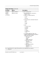
PATA Ch 0 Master. . . . . . . . . . . . . . . . . . . . . . . . . . . . . . . . . . . . . . . . . . . . . . . .   5
PATA Ch 0 Slave . . . . . . . . . . . . . . . . . . . . . . . . . . . . . . . . . . . . . . . . . . . . . . . . .   5
SATA Controller  . . . . . . . . . . . . . . . . . . . . . . . . . . . . . . . . . . . . . . . . . . . . . . . . .   6
PATA IDE Mode . . . . . . . . . . . . . . . . . . . . . . . . . . . . . . . . . . . . . . . . . . . . . . . . .   6
SATA Port . . . . . . . . . . . . . . . . . . . . . . . . . . . . . . . . . . . . . . . . . . . . . . . . . . . . . .   6
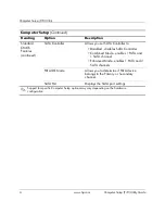
SATA Ch 0 Master. . . . . . . . . . . . . . . . . . . . . . . . . . . . . . . . . . . . . . . . . . . . . . . .   7
SATA Ch 1 Master. . . . . . . . . . . . . . . . . . . . . . . . . . . . . . . . . . . . . . . . . . . . . . . .   7
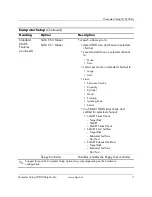
Floppy Controller . . . . . . . . . . . . . . . . . . . . . . . . . . . . . . . . . . . . . . . . . . . . . . . . .   7
Drive A . . . . . . . . . . . . . . . . . . . . . . . . . . . . . . . . . . . . . . . . . . . . . . . . . . . . . . . . .   8

Summary of Contents for Compaq dx2100

Page 1: ...tower Business PC Document Part Number 403287 001 September 2005 This guide provides instructions on how to use Computer Setup This tool is used to reconfigure and modify computer default settings when new hardware is installed and for maintenance purposes ...

Page 2: ...itorial errors or omissions contained herein This document contains proprietary information that is protected by copyright No part of this document may be photocopied reproduced or translated to another language without the prior written consent of Hewlett Packard Company Å WARNING Text set off in this manner indicates that failure to follow directions could result in bodily harm or loss of life Ä...

Page 3: ...rocessor Type 4 Processor Speed 4 CPU ID 4 Cache Size 4 DDR2 Memory Size 4 System ROM 4 Integrated MAC 4 UUID 4 System Serial Number 4 Asset Tracking Number 4 Asset Tag Number 4 Standard CMOS Features 4 Date mm dd yy 4 Time hh mm ss 4 PATA Controller 4 PATA Ch 0 Master 5 PATA Ch 0 Slave 5 SATA Controller 6 PATA IDE Mode 6 SATA Port 6 SATA Ch 0 Master 7 SATA Ch 1 Master 7 Floppy Controller 7 Drive ...

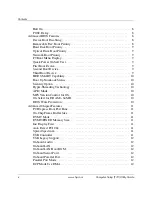
Page 4: ...apability 10 Boot Up NumLock Status 10 Security Option 10 Hyper Threading Technology 10 APIC Mode 10 MPS Version Control for OS 10 OS Select for DRAM 64MB 10 BIOS Write Protection 10 Advanced Chipset Features 11 PCI Express Root Port Func 11 On Chip Frame Buffer Size 11 DVMT Mode 11 DVMT FIXED Memory Size 11 Init Display First 11 Auto Detect PCI Clk 11 Spread Spectrum 11 USB Controller 11 USB Lega...

Page 5: ...nth Alarm 14 Time hh mm ss Alarm 14 PnP PCI Configurations 14 Reset Configuration Data 14 Resources Controlled By 14 IRQ Resources 15 Maximum Payload Size 15 PC Health Status 15 CPU Temperature 15 CPU Fan Speed 15 System Fan Speed 15 System Fan Fault Check 15 Load Optimized Defaults 15 Set Supervisor Password 16 Set User Password 16 Save Exit Setup 16 Exit Without Saving 16 Recovering the Configur...

Page 6: ...flash media devices Enable or disable Quick Power On Self Test which is faster than a full boot but does not run all of the diagnostic tests run during a full boot Enter the Asset Tag or property identification number assigned by the company to this computer Establish a supervisor password that controls access to Computer Setup F10 Utility and the settings described in this section To secure integ...

Page 7: ...t 2 As soon as the computer is turned on press and hold the F10 key until you enter Computer Setup If you do not press the F10 key at the appropriate time you must restart the computer and press and hold the F10 key again to access the utility 3 The Computer Setup Utility screen is divided into menu headings and actions Eight menu headings appear on the Computer Setup Utility screen System Informa...

Page 8: ...nd down keys to select the option you want then press Enter To return to the previous screen press Esc 4 To apply and save changes press F10 or select Save Exit Setup on the Computer Setup Utility screen and press Enter If you have made changes that you do not want applied select Exit Without Saving and press Enter Ä CAUTION Do NOT turn the computer power OFF while the ROM is saving the F10 Comput...

Page 9: ... DDR2 Memory Size view only System ROM view only Integrated MAC view only UUID view only System Serial Number view only Asset Tracking Number view only Asset Tag Number Enter asset tag number assigned by the company Standard CMOS Features Date mm dd yy Allows you to set system date Time hh mm ss Allows you to set system time PATA Controller Disables enables PATA Controller Support for specific Com...

Page 10: ...e Auto view Firmware Version Capacity Cylinder Head Precomp Landing Zone Sector run SMART HDD status check and self test for selected channel available if SMART IDE HDD installed SMART Status Check Target Disk SMART SMART Status Check SMART Short Self Test Target Disk Estimated Test Time Start Test SMART Extended Self Test Target Disk Estimated Test Time Start Test Computer Setup Continued Heading...

Page 11: ...oller Combined Mode enables 1 PATA and 1 SATA channel Enhanced Mode enables 1 PATA and 2 SATA channels PATA IDE Mode Allows you to determine if PATA device belongs to the Primary or Secondary channel SATA Port Displays the SATA port settings Computer Setup Continued Heading Option Description Support for specific Computer Setup options may vary depending on the hardware configuration ...

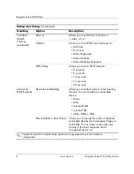
Page 12: ...ware Version Capacity Cylinder Head Precomp Landing Zone Sector run SMART HDD status check and self test for selected channel SMART Status Check Target Disk SMART SMART Status Check SMART Short Self Test Target Disk Estimated Test Time Start Test SMART Extended Self Test Target Disk Estimated Test Time Start Test Floppy Controller Disables enables the floppy disk controller Computer Setup Continue...

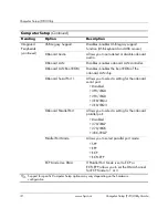
Page 13: ...nds 15 seconds 30 seconds Advanced BIOS Features Device Boot Disabling Allows you to restrict a device from booting the unit You can disable as a bootable device None USB Internal ODD Internal FDD USB ODD FDD Removable Dev Boot Priority Allows you to specify the order of attached removable devices such as Legacy Floppy or USB FDD The first drive in the order has priority in the boot sequence and i...

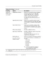
Page 14: ...specify the order in which network devices including UP NIC cards are checked for a bootable operating system image F9 Boot Menu Display Disables enables Boot Menu Quick Power On Self Test Disables enables the system to skip certain tests while booting Enabling this feature decreases the time required to boot the system First Boot Device Second Boot Device Third Boot Device Allows you to specify w...

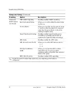
Page 15: ...per Threading Technology Disables enables hyper threading only available for operating systems that are optimized for hyper threading technology APIC Mode Disables enables the APIC mode MPS Version Control for OS Allows you to set the MPS table version to 1 1 1 4 OS Select for DRAM 64MB Allows you to select Non OS2 or OS2 Select OS2 only if running an OS2 operating system with greater than 64MB of...

Page 16: ...et DVMT Mode to Fixed DVMT Both DVMT FIXED Memory Size VGA Setting Allows you to set memory size to 64MB 128MB Init Display First VGA Setting Allows you to set initiation priority of graphics display to PCI Slot Onboard Auto Detect PCI Clk VGA Setting Disables enables PCI clock auto detection Spread Spectrum VGA Setting Disables enables clock spread spectrum Integrated Peripherals USB Controller D...

Page 17: ... Onboard Serial Port 1 Allows you to select a setting for the onboard serial port Disabled 3F8 IRQ4 2F8 IRQ3 3E8 IRQ4 2E8 IRQ3 Onboard Parallel Port Allows you to select a setting for the onboard parallel port Disabled 378 IRQ7 278 IRQ5 3BC IRQ7 Parallel Port Mode Allows you to select parallel port mode SPP EPP ECP ECP EPP ECP Mode Use DMA If Parallel Port Mode is set to ECP or ECP EPP allows you ...

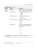
Page 18: ...S3 STR S1 S3 Soft Off by Power Button Allows you to set power button to Instant off Delay 4 seconds Power On After Power Fail Allows you to select system power loss behavior Last State On Off MODEM Use IRQ Allows you to select IRQ for MODEM to use Select NA to disable external MODEM wake up function NA 3 4 5 7 9 10 11 Computer Setup Continued Heading Option Description Support for specific Compute...

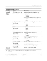
Page 19: ...tic reconfiguration The default is Disabled Select Enabled to reset Extended System Configuration Data ESCD when you exit Setup if you have installed a new add on and the system reconfiguration has caused such a serious conflict that the OS cannot boot Resources Controlled By Allows you to select whether resources are controlled automatically or manually Auto ESCD Extended Storage Configuration Da...

Page 20: ...pliant with the original PC AT bus specification PCI ISA PnP for devices compliant with the Plug and Play standard whether designed for PCI or ISA bus architecture Maximum Payload Size Allows you to set TLP payload size for the PCI Express Devices to in bytes 128 256 512 1024 2048 4096 PC Health Status CPU Temperature view only CPU Fan Speed view only System Fan Speed view only System Fan Fault Ch...

Page 21: ...r Password Allows you to establish a password to control access to the computer Save Exit Setup Allows you to save current settings and exit Computer Setup Exit Without Saving Allows you to exit Computer Setup without saving changes Computer Setup Continued Heading Option Description Support for specific Computer Setup options may vary depending on the hardware configuration ...

Page 22: ...s to a diskette a USB flash media device or a diskette like device a storage device set to emulate a diskette drive and save the diskette or device for possible future use Backing up the CMOS 1 Make sure the computer to be backed up is turned on Connect the removable storage to the computer 2 Boot to DOS 3 Type N folder BIOS exe SAVE ABC001 DAT where N is the drive letter of the removable storage ...

Reviews: