


Troubleshooting Guide www.hp.com/in 8-12
Troubleshooting
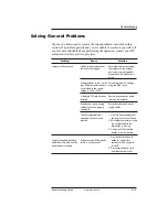
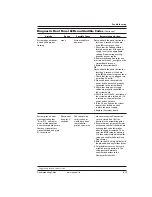
Solving General Problems
You may be able to easily resolve the minor problems described in this
section. If a problem persists and you are unable to resolve it yourself or if
you feel uncomfortable about performing the operation, contact your HP
authorized reseller or service provider.
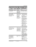
Problem
Computer will not turn on.
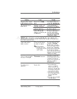
Computer appears locked up
and will not turn off when the
power button is pressed.
Cause
Cables to the external power
source are unplugged.
Voltage selector switch* on the
rear of the computer chassis is
not switched to the correct
voltage (115V or 230V).
A defective PCI card has been
installed.
Drive data or power supply
cables may not be properly
connected.
The unit temperature was
exceeded. The fan may be
blocked.
Software control of the power
switch is not functional.
Solution
Ensure that cables connecting
the computer to the external
power source are plugged in
properly and the wall outlet is
active.
Select the proper AC voltage
using the slide switch.
Remove any expansion board
that was just installed.
Reseat drive data and power
supply cables.
1. Unit is in an exceedingly hot
environment. Let it cool down.
2. Ensure that computer air vents
are not blocked and the
internal fan is running.
3. Contact an HP authorized
reseller or service provider.
1. Press and hold the power
button for at least four
seconds until the computer
turns off.
2. Disconnect the power cord
from the electrical outlet.


