


2-8
www.hp.com
Hardware Reference Guide
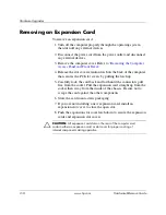
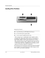
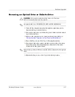
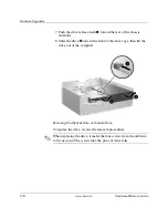
Hardware Upgrades
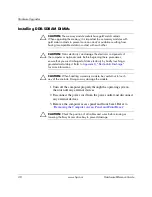
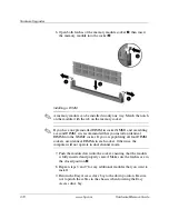
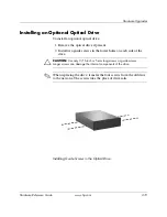
Installing DDR-SDRAM DIMMs
Ä
CAUTION:
The memory module sockets have gold metal contacts.
When upgrading the memory, it is important to use memory modules with
gold metal contacts to prevent corrosion and/or oxidation resulting from
having incompatible metals in contact with each other.
Ä
CAUTION:
Static electricity can damage the electronic components of
the computer or optional cards. Before beginning these procedures,
ensure that you are discharged of static electricity by briefly touching a
grounded metal object. Refer to
Appendix D, “Electrostatic Discharge”
for more information.
Ä
CAUTION:
When handling a memory module, be careful not to touch
any of the contacts. Doing so may damage the module.
1. Turn off the computer properly through the operating system,
then turn off any external devices.
2. Disconnect the power cord from the power outlet and disconnect
any external devices.
3. Remove the computer access panel and front bezel. Refer to
“Removing the Computer Access Panel and Front Bezel.”
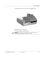
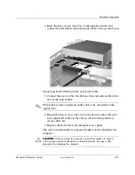
Ä
CAUTION:
Check the position of all cables and wires before raising or
lowering the Easy Access drive bay to prevent damage.


