Index–4
Maintenance and Service Guide
Index
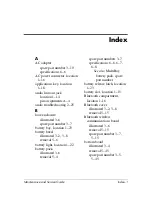
K
keyboard
components
1–17
illustrated
3–2
removal
5–17
spare part numbers
3–3
,
5–17
troubleshooting
2–28
keyboard plate
illustrated
3–2
,
3–8
removal
5–25
L
LED board
illustrated
3–6
removal
5–43
spare part number
3–7
,
5–43
left-side components
1–13
M
mass storage devices, spare
part numbers
3–9
memory expansion board
illustrated
3–4
removal
5–21
spare part numbers
3–5
,
5–21
memory shield
illustrated
3–2
,
3–8
removal
5–21
microphone jack
location
1–14
pin assignments
A–4
Mini PCI communications
board
illustrated
3–6
removal
5–10
spare part numbers
3–7
,
5–10
Mini PCI compartment cover
illustrated
3–2
,
3–8
removal
5–10
Mini PCI compartment,
location
1–24
Miscellaneous Plastics Kit
components
3–8
spare part number
3–3
,
3–8
model number
3–1
models
1–2
modem board
illustrated
3–4
removal
5–20
spare part number
3–5
,
5–20
modem jack, pin assignments
A–2
modem, troubleshooting
2–30
monitor connector
location
1–16
pin assignments
A–3
mouse, spare part number
3–11
MultiBay battery pack
spare part number
3–7
,
3–9
MultiBay device
illustrated
3–6
spare part numbers
3–9
MultiBay light, location
1–22

