background image

11-15

Compaq Professional Workstation SP700 Reference Guide

Writer: kmosby   Project: Compaq Professional Workstation SP700 Reference Guide   Comments: 320280-002

File Name: L-CH11.DOC   Last Saved On: 12/11/98 4:29 PM

COMPAQ CONFIDENTIAL - NEED TO KNOW REQUIRED
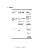
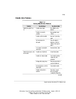
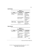
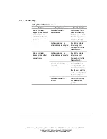
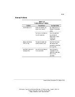
Memory Problems

Table 11-8

Solving Memory Problems

Problem

Possible Cause

Possible Solution

Out of Memory error.

Memory configuration may

not be set up correctly.

Run Computer Setup or

Windows NT Workstation

utilities.

You have run out of memory

to run the application.

Check the application

documentation to

determine the memory

configuration

requirements.

Memory count during

POST is wrong.

The memory modules may

not be installed correctly.

Check that the memory

modules have been

installed correctly and run

the Setup utility.

Insufficient memory error

during operation.

You have run out of memory

for your application.

Check the memory

requirements for the

application, or add more

memory to the

workstation.

Summary of Contents for Compaq SP700

Page 1: ...Professional Workstation SP700 Reference Guide Second Edition February 1999 Part Number 320280 002 Compaq Computer Corporation ...

Page 2: ...d in any form without prior written consent from Compaq Computer Corporation 1998 Compaq Computer Corporation All rights reserved Printed in the U S A The software described in this guide is furnished under a license agreement or nondisclosure agreement The software may be used or copied only in accordance with the terms of the agreement Compaq Fastart ROMPaq QVision SmartStart NetFlex QuickFind a...

Page 3: ...atures 1 2 SmartStart for Workstations 1 6 Front Panel Components 1 7 Rear Panel Components 1 9 Side View Components 1 11 Keyboard and Mouse 1 12 Special Mouse Functions 1 12 Special Keyboard Functions 1 12 Windows Logo Key 1 15 Keyboard Lights 1 16 Chapter 2 Compaq Setup and Diagnostic Software Computer Setup 2 1 Using Computer Setup 2 2 Compaq Diagnostics 2 6 Computer Checkup TEST 2 6 View Syste...

Page 4: ... 3 8 Disabling a Serial Port or Parallel Port 3 9 Password Security 3 10 Cable Lock Provision 3 16 Configuration Management 3 18 Upgrading the ROM 3 19 FailSafe Boot Block ROM 3 21 Remote Security Management 3 24 Remote Wakeup and Remote Shutdown 3 25 Remote System Installation 3 26 Replicating Your Setup 3 26 Power Management 3 27 Advanced Configuration and Power Interfaces ACPI Ready Hardware 3 ...

Page 5: ...2 Reconfiguring the Workstation 6 3 Removing the Side Access Panel 6 4 Removing the Front Bezel 6 5 Identifying the Internal Components 6 6 Removing the Expansion Board Assembly 6 8 Reinstalling the Expansion Board Assembly 6 9 Removing the Removable Hard Drive Cage 6 10 Identifying the System Board Components 6 12 Chapter 7 Memory Upgrades Installing Additional Memory 7 1 Important Guidelines for...

Page 6: ... a PCI or an ISA Expansion Board 9 4 Identifying the Accelerated Graphics Port AGP Graphics Controller Expansion Slot 9 6 Installing and Removing an AGP Graphics Controller 9 6 Installing a Wide Ultra2 PCI Controller 9 7 Chapter 10 Processors Installing an Additional Processor 10 1 Upgrading the Processor 10 4 Chapter 11 Troubleshooting Checklist for Minor Problems 11 1 Troubleshooting Common Prob...

Page 7: ... Products Marked with FCC Logo United States Only A 3 Mouse Compliance Statement A 4 Canadian Notice Avis Canadien A 4 Class A Equipment A 4 Class B Equipment A 4 European Union Notice A 4 Japanese Notice A 5 Taiwanese Notice A 5 Laser Devices A 6 Laser Safety Warnings A 6 Compliance with CDRH Regulations A 6 Compliance with International Regulations A 6 Laser Product Label A 7 Laser Information A...

Page 8: ... Reference Guide Comments 320280 002 File Name A FRNT DOC Last Saved On 12 16 98 1 44 PM COMPAQ CONFIDENTIAL NEED TO KNOW REQUIRED Appendix E Installing a New Battery Running Computer Setup E 1 Installation Procedures E 2 Appendix F Workstation Specifications Index ...

Page 9: ... the following conventions to distinguish elements of text Keys Keys appear in boldface A plus sign between two keys indicates that they should be pressed simultaneously USER INPUT User input appears in a different typeface and in uppercase FILENAMES File names appear in uppercase italics Menu Options Command Names Dialog Box Names These appear in initial capital letters COMMANDS DIRECTORY NAMES a...

Page 10: ...ols may be found in the text of this guide They have the following meanings WARNING Indicates that failure to follow directions in the warning could result in bodily harm or loss of life CAUTION Indicates that failure to follow directions could result in damage to equipment or loss of information IMPORTANT Presents clarifying information or specific instructions NOTE Presents commentary sidelights...

Page 11: ...electrical shock fire or damage to the equipment do not plug telephone or telecommunications connectors into this receptacle Any surface or area of the equipment marked with these symbols indicates the presence of a hot surface or hot component If this surface is contacted the potential for injury exists WARNING To reduce the risk of injury from a hot component allow the surface to cool before tou...

Page 12: ...g locations Compaq Website The Compaq website has information on this product as well as the latest drivers and Flash ROM images You can access the Compaq website by logging on to the Internet at www compaq com Telephone Numbers For the name of your nearest Compaq Authorized Reseller In the United States call 1 800 345 1518 In Canada call 1 800 263 5868 For Compaq technical support In the United S...

Page 13: ...Kmosby Project Compaq Professional Workstation SP700 Reference Guide Comments 320280 002 File Name B CH01 DOC Last Saved On 1 18 99 11 38 AM COMPAQ CONFIDENTIAL NEED TO KNOW REQUIRED Chapter 1 Product Features COMPAC T Figure 1 1 Compaq Professional Workstation SP700 ...

Page 14: ...00 MHz Pentium II Xeon 450 MHz or Pentium III Xeon 500 MHz processor Number of Processors One processor upgradable to two L2 Cache Size 512 KB 1 MB PCI Bus Dual Peer PCI buses aggregate bandwidth of 267MB sec AGP Bus 2x mode capable 533 MB sec bandwidth and supports Side Band Addressing SBA Memory Controller Dual 64 bit memory controllers aggregate bandwidth of 1 6GB sec Memory 100 MHz ECC Registe...

Page 15: ...PCI ISA slot two short ISA slots and one Accelerated Graphics Port AGP slot located on system board Drive Controller Integrated IDE controller Dual Wide Ultra SCSI Wide Ultra2 SCSI controller on select models Network Controller Compaq NC3161 Fast Ethernet NIC Embedded 10 100 WOL Hard Drive Types Wide Ultra SCSI or Wide Ultra2 SCSI To find your specific hard drive size double click on My Computer t...

Page 16: ...A and B Parallel USB two available hardware ready Wide Ultra SCSI channel 2 Wide Ultra2 SCSI on select models Ethernet RJ 45 IEEE 1394 two available Headphone and microphone jacks Keyboard Mouse VGA AGP on selected models Stereo line in line out MIDI game Audio Integrated speaker built into the front bezel Integrated 16 bit audio Headphone jack Microphone jack MIDI game Stereo line in line out ROM...

Page 17: ...Remote Wakeup and Remote Shutdown Establishment of Power Management Settings Advanced Configuration and Power Interface ACPI capable Compaq Support Software CD Kit and support from Compaq website DMI 2 0 For more information see Chapter 3 Asset Management Compaq Diagnostics for Windows NT For more information see Chapter 3 Security Features Keyboard password Administrator password Diskette Write C...

Page 18: ...e using SmartStart for Workstations For more information about SmartStart for Workstations refer to the Software Installation Guide shipped with the workstation There are also online help files located on the SmartStart for Workstations CD For information about the graphics controller installed on your workstation refer to the appropriate guide on the SmartStart for Workstations CD under X DOCS GR...

Page 19: ... Guide Comments 320280 002 File Name B CH01 DOC Last Saved On 1 18 99 11 38 AM COMPAQ CONFIDENTIAL NEED TO KNOW REQUIRED Front Panel Components The following figure identifies the front panel components Refer to Table 1 2 for a description of each component 3 2 1 4 6 7 8 9 COMPACT 5 Figure 1 2 Identifying front panel components ...

Page 20: ...wer button if the LED is Steady Green Workstation is turned on and both the expansion board assembly and the processor processor terminator board are seated properly Blinking green Workstation is in standby mode Power button Turns the workstation on or off Hard drive activity LED When lit indicates the workstation is reading or writing data to the hard drive s Network activity LED When lit indicat...

Page 21: ...nectors and jacks Refer to the corresponding table for a description of each component 1 2 3 4 6 9 12 14 5 7 11 10 8 17 13 15 16 Figure 1 3 Identifying rear panel components Table 1 3 Rear Panel Components Ref Component Function Power cord connector Connects the power cord Headphone jack Connects to headphones Audio line out connector Connects to an external amplifier that powers additional speake...

Page 22: ...a serial device Microphone jack Connects to a microphone Keyboard connector Connects to a keyboard orange icon IEEE1394 connectors 2 Connect to IEEE 1394 devices Mouse connector Connects to a mouse green icon Wide Ultra SCSI connector channel 2 Connects Channel 2 of the integrated Dual Wide Ultra SCSI to a SCSI device Parallel connector Connects to a parallel device such as a printer RJ 45 connect...

Page 23: ...identifies the components from the side view of the workstation and with the side access panel removed Refer to the corresponding table for a description of each component 5 6 7 8 COMPACT 4 3 2 1 Figure 1 4 Identifying components from side view Table 1 4 Side View Components Ref Component Description 1 Bay 1 3 5 inch drive Part of removable hard drive cage 2 Bay 2 3 5 inch drive Part of removable ...

Page 24: ...ips with a keyboard and a three button mouse Special Mouse Functions Most software applications support the use of a mouse The functions assigned to each mouse button depend on the software application you are using The Logitech OEM MouseWare software provides special drivers and an applet that allows you to define the functionality of the mouse buttons For more information on installing this soft...

Page 25: ... kmosby Project Compaq Professional Workstation SP700 Reference Guide Comments 320280 002 File Name B CH01 DOC Last Saved On 1 18 99 11 38 AM COMPAQ CONFIDENTIAL NEED TO KNOW REQUIRED 1 2 13 3 4 5 6 7 9 12 10 11 8 9 11 10 Figure 1 5 Identifying Special Function keys ...

Page 26: ...Lock light is on the screen is prevented from scrolling 6 Pause Temporarily suspends screen scrolling or some operations 7 Num Lock When the Num Lock light is on the numeric keypad is activated and the arrow keys are deactivated The arrow keys to the left of the keypad perform the same functions as the arrow keys on the keypad 8 Caps Lock When the Caps Lock light is on all letters typed are capita...

Page 27: ...her keys to perform certain functions in Windows NT Workstation Table 1 6 Key Combinations Windows Logo Key Combination Function in Windows NT Workstation Windows logo key F1 Displays a pop up menu for the selected object Windows logo key Tab Activates the next Taskbar button Windows logo key E Launches Explore My Computer Windows logo key F Launches Find Document Windows logo key Ctrl F Launches ...

Page 28: ...fies the location of the three keyboard lights For a description of each light refer to the corresponding table 1 2 3 Figure 1 6 Keyboard lights Table 1 7 Keyboard Lights Ref Description Function Num Lock When Num Lock is enabled light is on the numeric keypad is activated Caps Lock When the Caps Lock is enabled light is on all text appears in uppercase when typed Scroll Lock When Scroll Lock is e...

Page 29: ...omputer Setup allows you to configure your workstation s hardware and resolve resource conflicts Computer Setup provides information you will need about your workstation if you need assistance from Compaq Customer Support Setup can also be used To change factory default settings and to set or change the system configuration which may be necessary when you add or remove hardware To determine if all...

Page 30: ...st turn the workstation off then on again to access the utility The F12 key initiates Network Service Boot for Remote System installation See Chapter 3 for more information about this feature 3 The Computer Setup menu appears with the following menu headings File Storage Security Power and Advanced See Table 2 1 for a description of the features available in Computer Setup 4 Press the arrow keys o...

Page 31: ...ette drives Select Storage then select Diskette Drives Enable disable diskette booting and diskette writing NOTE After saving changes to Removable Media the workstation should be restarted for the changes to take effect Turn the workstation off then on manually Select Storage then select Removable Media View information regarding IDE devices connected to the system NOTE ATAPI devices CD ROM tape a...

Page 32: ... This selection appears only if a Power on Password is set Select Security then select Password Options Enable the Setup administrator Password For more information see the section Security Management in Chapter 3 Select Security then select Setup Password Enable disable serial parallel and USB ports and audio security Select Security then select Device Security Set the Asset Tag and Ownership Tag...

Page 33: ...stering PCI reset on warm boot and PCI VGA palette snooping Select Advanced then select Bus Options Set ISA back to back I O fast legacy delay and bus priority ISA PCI Select Advanced then select Bus Options Set the printer mode flexible standard Select Advanced then select Device Options Set the Num Lock state at power on Select Advanced then select Device Options Specify which VGA controller is ...

Page 34: ...ussed in Chapter 3 Computer Checkup TEST NOTE Computer Checkup will detect Compaq hardware Devices from other manufacturers may not be detected Use Computer Checkup TEST in the following instances To determine if all the devices installed on the workstation are recognized by the system and functioning properly Running TEST is optional but recommended after installing or connecting a new device To ...

Page 35: ... to the Compaq Customer Support Center To assist your Compaq authorized dealer reseller or service provider in analyzing the system by allowing the service provider to reproduce the same environment on another workstation for testing The information provided by INSPECT includes Contents of the operating system startup files Current memory configuration ROM versions Type of processor and coprocesso...

Page 36: ...l System Configuration 4 Click Install Optional Compaq Software 5 Click Create a Diagnostics Diskette and follow the instructions on the screen Using Computer Checkup TEST or View System Information INSPECT IMPORTANT Before you run Computer Checkup TEST or View System Information INSPECT you must create a diagnostics diskette For instructions see the section Creating a Diagnostics Diskette in this...

Page 37: ...uthorized dealer reseller or service provider 3 Select one of the following from the test option menu Quick Check Diagnostics This option runs a quick general test on each device with a minimal number of prompts If errors occur they are displayed when the testing is complete Automatic Diagnostics This option runs unattended maximum testing of each device with minimal prompts You can choose how man...

Page 38: ...ests called Power On Self Tests POSTs These tests check and initialize many hardware components The basic sequence for POST is 1 Check and initialize low level hardware 2 Count memory 3 Initialize processor s 4 Detect and spin up all drives 5 Boot from in sequence either a CD a diskette or the hard drive Refer to Appendix D POST Error Messages for a listing of POST error codes and steps you can ta...

Page 39: ... Since the BIOS is stored in ROM on the system board the upgrade procedure is different than the upgrade procedure for other software New versions of BIOS may be downloaded from the Compaq website at www compaq com BIOS upgrades are called ROMPaq To upgrade your ROM BIOS execute the ROMPaq software and follow the directions Boot Block ROM The Boot Block ROM cannot be upgraded For more information ...

Page 40: ...IAL NEED TO KNOW REQUIRED Chapter 3 Intelligent Manageability Intelligent Manageability combines innovative hardware technology with systems management tools from Compaq and other leading vendors to make Compaq workstations easier to inventory troubleshoot protect and maintain Intelligent Manageability features focus on Asset Management Fault Management Security Management Configuration Management...

Page 41: ...el and serial number of Compaq workstations monitors hard drives and dual inline memory modules DIMMs Asset Tag System board and ROM revision level Allow you to view print or electronically save this data and other system configuration details using Compaq Diagnostics for Windows NT Compaq Insight Manager System management products from the Compaq Management Solutions Partners Management software ...

Page 42: ...ation Memory configuration Security management settings System health Operating system Windows version To install Compaq Diagnostics for Windows NT refer to the Software Installation Guide Using Compaq Diagnostics for Windows NT 1 Select the Compaq Diagnostics for Windows NT icon or the Compaq Diagnostics icon located in the Control Panel The screen displays an overview of the workstation hardware...

Page 43: ...ort All Categories Summary Report All Categories or Current Category Click OK to print the report you selected 5 To exit Compaq Diagnostics for Windows NT click File then click Exit Fault Management Fault Management features combine innovative hardware and software technology to prevent the loss of critical data and minimize unplanned downtime When a fault occurs the workstation displays a Local A...

Page 44: ...s to flag potentially bad areas of the disk With today s multi gigabyte hard drives there are areas of the disk that are not read or written by applications for long periods of time The SMART III technology will patrol the entire disk so that when unused or infrequently used parts of the disk are called upon the data will be available ECC Fault Prediction and Prefailure Warranty When the workstati...

Page 45: ...ou time to take action before internal components are damaged or data is lost Security Management Your workstation includes security features to protect the workstation and data from unauthorized access You can view Security Management features and current settings by using Compaq Diagnostics for Windows NT locally Compaq Management Agents for Workstations remotely Compaq Remote Management Setup r...

Page 46: ...ED Security Features Continued Feature Purpose Setup Password Prevents reconfiguration of the workstation the use of the Computer Setup utility until the password is entered Cable Lock Provision Inhibits access to the interior of the workstation which prevents unwanted configuration changes or component removal IDE Controller Prevents the transfer of data through the IDE interface The following su...

Page 47: ...able the factory settings that is to prevent boot from a diskette or prevent save to a diskette follow these steps 1 Turn on or restart the workstation 2 When you see the words F10 Setup in the bottom right corner of the screen press the F10 key NOTE If you do not press the F10 key while the message is displayed you must turn off the workstation then on again to access the utility 3 From the main ...

Page 48: ...e steps 1 Turn on or restart the workstation 2 When you see the words F10 Setup in the bottom right corner of the screen press the F10 key NOTE If you do not press the F10 key while the message is displayed you must turn off the workstation then on again to access the utility 3 From the main menu select Advanced then select Onboard Devices 4 Press the up down arrow keys to select the Serial or Par...

Page 49: ...etup Establishing a Setup Password through Computer Setup prevents reconfiguration of the workstation use of the Computer Setup utility until the password is entered 1 Turn on or restart the workstation 2 When you see the words F10 Setup in the bottom right corner of the screen press the F10 key NOTE If you do not press the F10 key while the message is displayed you must turn off the workstation t...

Page 50: ...ttom right corner of the screen press the F10 key NOTE If you do not press the F10 key while the message is displayed you must turn off the workstation then on again to access the utility 3 From the main menu select Security then select Power On Password and follow the instructions on the screen 4 Save the configuration and exit the utility 5 Restart the workstation Entering a Power on Password To...

Page 51: ...shown current password new password new password NOTE Type carefully for security reasons the characters you type do not appear on the screen Refer to the section National Keyboard Delimiter Characters in this chapter for information about the alternate delimiter characters The new password takes effect the next time you turn on the workstation Deleting a Power on or Setup Password 1 Turn on or re...

Page 52: ...urn off the workstation Disconnect the power cord from the grounded AC outlet and from the power connector on the rear of the workstation 2 Remove the following components side access panel expansion board assembly 3 On SW1 move switch position 6 to the ON position on 6 5 4 3 2 1 SW1 Figure 3 1 Locating the default SW1 switch IMPORTANT Switch 6 has a default setting of OFF When the switch is OFF y...

Page 53: ... clear the Setup Password Be sure to reestablish your Setup Password after clearing the Power on Password 6 Turn off the workstation once more Disconnect the power cord from the grounded AC outlet and from the power connector on the rear of the workstation 7 Remove the side access panel and the expansion board assembly to access SW1 on the system board 8 Return switch 6 to its original default OFF...

Page 54: ...ntry specific requirements The syntax and keys that you use for changing or deleting your password depend on the keyboard that came with your workstation Table 3 2 National Keyboard Delimiter Characters Arabic Greek Russian Belgian Hebrew Slovakian BHCSY Hungarian Spanish Brazilian Italian Swedish Finnish Chinese Japanese Swiss Czech Korean Taiwanese Danish Latin American Thai French Norwegian Tur...

Page 55: ...ty bracket can be used with a padlock to inhibit access to the interior of the workstation which prevents unwanted configuration changes or component removal For increased security a cable lock can be installed to secure the workstation to a fixed object To install the security bracket 1 Separate bracket A and bracket B by bending the metal back and forth where the two pieces join B A Figure 3 2 S...

Page 56: ...D 4 Install the retaining screw provided in the cable lock kit A Figure 3 3 Installing bracket A 5 Place bracket B over bracket A to cover the retaining screw 6 Install a padlock not provided through bracket A to inhibit access to the interior of the workstation Or to inhibit access to the interior of the workstation and secure the workstation to a fixed object install a cable lock not shown A B F...

Page 57: ...rading the ROM Local ROM Flash Remote ROM Flash FailSafe Boot Block ROM Remote Security Management Remote Wakeup and Remote Shutdown Remote System Installation Dual State Power Button Power Management Advanced Configuration and Power Interface ACPI ready hardware Compaq Support Software CD Kit and support from the Compaq website NOTE Your workstation must be connected to a network to take advantag...

Page 58: ...ad the latest ROMPaq images from the Compaq website at www compaq com CAUTION For maximum ROM protection be sure to establish a Setup Password The Setup Password prevents unauthorized ROM upgrades Local ROM Upgrade To upgrade the ROM after you receive or download a user ROMPaq diskette follow these steps 1 Insert the user ROMPaq diskette in the diskette drive and boot the workstation 2 Enter the S...

Page 59: ... is protected during the flash process and allows the workstation to be restarted in the unlikely event of an unsuccessful ROM Flash Remote ROM Flash is performed in two stages 1 The system administrator uses the Remote Management Setup software on a centralized management console to prepare a workstation ROMPaq file 2 The system administrator uses a PC LAN management product such as Microsoft SMS...

Page 60: ...he workstation ships with the diskette drive enabled If the diskette drive is disabled the FailSafe Boot Block ROM will override the disabled component to accommodate a system ROM recovery in the event a system ROM failure occurs Because there is no video or hard drive support from the Boot Block ROM the keyboard lights communicate information When the Boot Block detects an invalid system ROM the ...

Page 61: ...ll Lock Meaning and Required Action OFF ON OFF System requires Setup Password Enter the Setup Password The light remains turned on until you enter a valid Setup Password ON OFF OFF System could not start from diskette because the user ROMPaq diskette is not present is bad or the drive is not ready Insert a valid user ROMPaq diskette turn the power off then turn the power on OFF OFF ON ROM upgrade ...

Page 62: ...00 Reference Guide Writer kmosby Project Compaq Professional Workstation SP700 Reference Guide Comments 320280 002 File Name D CH03 DOC Last Saved On 1 18 99 11 43 AM COMPAQ CONFIDENTIAL NEED TO KNOW REQUIRED 1 2 3 Figure 3 5 Keyboard lights ...

Page 63: ... of ownership NOTE Your workstation must be powered on or turned on through Remote Wakeup to take advantage of Remote Security Management Use of Remote Security Management also requires an established Setup Password Remote Security Management is performed in two stages 1 The system administrator uses the Remote Management Setup software on a centralized management console to define the security pa...

Page 64: ...nt tools NOTE Third party software tools are required to remotely distribute software Remote Wakeup allows the network interface controller to continue functioning even when power to the workstation has been turned off NOTE The workstation continues to consume a small amount of electricity even after you turn it off Only when you disconnect the power cord from the electrical outlet does the workst...

Page 65: ...see the words F12 Network Service Boot in the bottom right corner of the Compaq logo screen Follow the instructions on the screen to continue the process Replicating Your Setup This procedure gives an administrator the ability to easily copy one setup configuration to other workstations of the same model This allows for faster more consistent configuration of multiple workstations To replicate you...

Page 66: ...ent settings for the monitor To access Display Properties right click on the Windows NT Workstation desktop then select Properties Advanced Configuration and Power Interfaces ACPI Ready Hardware ACPI defines a hardware interface that allows a standard way to integrate power management features throughout the workstation system including hardware operating system and application software This enabl...

Page 67: ...it and the website include The Locator with Decision Support a comprehensive listing of the device drivers utilities flashable ROM images and more categorized by operating system computer family and model for easy retrieval Decision Support provides detailed information for each piece of support software including descriptions features enhancements dependencies and critical updates If you choose t...

Page 68: ...ardize access to PC configuration data Compaq as a Steering Committee and Technical Committee member of the DMTF delivers hardware and software instrumentation that supports the DMI standard Compaq Management Agents for Workstations Using the industry standard Simple Network Management Protocol SNMP found in Microsoft Windows NT Workstation Compaq Management Agents for Workstations allows the syst...

Page 69: ...anageability features with leading systems management products The partnership ensures that the benefits of Intelligent Manageability are accessible through a broad range of vendors This allows customers to use their tools of choice to remotely manage their Compaq workstations more confidently and cost effectively Compaq Management Solutions Partners include BindView BindView Console Intel LANDesk...

Page 70: ...e and run common software programs NOTE For more information about installing your network driver refer to the Software Installation Guide Your workstation comes Ethernet network ready which means that it has a preinstalled network controller and preinstalled network drivers The Compaq NC3161 Fast Ethernet NIC Embedded 10 100 WOL is a PCI bus mastering dual speed 10BaseT and 100BaseTX controller t...

Page 71: ...BaseTX network you must use a Category 5 UTP cable Figure 4 1 Attaching the network cable to the RJ 45 connector Any RJ 45 receptacle marked with these symbols indicates a Network Interface Connection WARNING To reduce risk of electrical shock fire or damage to the equipment do not plug telephone or telecommunications connectors into this receptacle Installing the Network Driver The network device...

Page 72: ...udes a CD ROM drive or DVD ROM drive IDE and a PremierSound Audio System The CD ROM drive or DVD ROM drive is a random access read only storage device capable of retrieving data from a removable CD The PremierSound Audio System provides sound capabilities for increased productivity in the Microsoft Windows NT Workstation operating environment Using the Tray to a Load CD ROM Drive or DVD ROM Drive ...

Page 73: ...revent accidental damage to the disc If the Eject button is disabled by the application software it will not operate Using CD ROM or DVD ROM Software The first time you use a software program that comes on a compact disc it may load a certain amount of program data onto the hard drive of your workstation This enables the program to run more efficiently and quickly in the future NOTE Some software ...

Page 74: ...tions Do not move the drive during operation This may cause it to malfunction during reading Avoid exposing the drive to sudden changes in temperature because condensation may form inside the unit If the temperature suddenly changes while the drive is on wait at least one hour before you turn off the power If you operate the unit immediately it may malfunction while reading Avoid placing the drive...

Page 75: ... for example you can enhance presentation data with voice and music If you choose to upgrade your audio system you must disable the integrated audio controller IMPORTANT Do not remove the ESS 1869 driver from the Drivers window in the Control Panel Follow the instructions below 1 From the Control Panel in Windows NT Workstation select Devices 2 From the Devices window select the AudioDrive device ...

Page 76: ...uring the workstation is also discussed to ensure that newly installed components are recognized by your system This chapter also identifies all internal components IMPORTANT Compaq recommends that you finish the setup procedures for the preinstalled software before you install any optional hardware or third party devices that were not included with the workstation For more information about the s...

Page 77: ...kstation or optional equipment Before beginning these procedures ensure that you are discharged of static electricity by briefly touching a grounded metal object Refer to Appendix B for more information 1 Turn off the workstation and disconnect the power cord from the grounded AC outlet and the back of the workstation 2 Open the workstation by removing the side access panel and the front bezel Ref...

Page 78: ...the Workstation System configuration is the process of specifying the devices and programs that make up a system When you add or remove optional equipment you must reconfigure the workstation by running Computer Setup in order for the changes to be recognized Run the Computer Setup utility after you complete the hardware installation To configure in Windows NT Workstation use the Control Panel and...

Page 79: ...f the workstation and disconnect the power cord from the grounded AC outlet and the back of the workstation 2 Refer to the following illustration to remove the side access panel Figure 6 1 Loosening the four rear panel thumbscrews and removing the side access panel IMPORTANT When replacing the side access panel be sure to tighten all four thumbscrews NOTE The hood labels attached to the inside of ...

Page 80: ... Removing the Front Bezel You will need to remove the front bezel when you are installing or removing drives in the front bay To remove the front bezel 1 Turn off the workstation and disconnect the power cord from the grounded AC outlet and the back of the workstation 2 Remove the side access panel 3 Refer to the following illustration to remove the front bezel COMPACT 1 2 Figure 6 2 Pressing fron...

Page 81: ...ONFIDENTIAL NEED TO KNOW REQUIRED Identifying the Internal Components The following illustration and table identify the internal components of your workstation 2 3 4 5 6 8 9 10 COMPACT 1 7 Figure 6 3 Identifying internal components Table 6 1 Internal Components Ref Component CD ROM drive or DVD ROM drive drive bay 4 5 25 inch drive bay drive bay 5 5 25 inch drive bay drive bay 6 Continued ...

Page 82: ...Speaker with PremierSound and fixed equalization Power supply 3 5 inch removable hard drive cage that supports either three 1 0 inch drives or two 1 6 inch drives Drive bay 1 on bottom drive bay 2 in middle and drive bay 3 on top Expansion board assembly includes riser board PCI expansion slots and ISA expansion slots System board includes SW1 switch AGP slot 8 DIMM sockets two processor slots and...

Page 83: ...he back of the workstation 2 Remove the side access panel 3 Refer to the following illustration to remove the expansion board assembly Figure 6 4 Removing the expansion board assembly 4 Reassemble the workstation and connect the power cord to the grounded AC outlet and to the workstation IMPORTANT After connecting the power cord to the grounded AC outlet and to the workstation DO NOT turn the powe...

Page 84: ...e Expansion Board Assembly To reinstall an expansion board assembly follow these steps 1 Turn off the workstation Disconnect the power cord from the grounded AC outlet and from the back of the workstation 2 Slide the expansion board assembly into the chassis aligning the guide rails and tab s 3 Align the holes in the back of the chassis 3 4 Press the expansion board assembly firmly over the connec...

Page 85: ...g the Removable Hard Drive Cage To remove the removable hard drive cage 1 Turn off the workstation and disconnect the power cord from the grounded AC outlet and from the back of the workstation 2 Remove the side access panel 3 Unscrew the thumbscrews on top of the cage 1 Hold the tab and pull the cage up and out of the workstation chassis 2 1 1 2 Figure 6 6 Loosening the two thumbscrews and removi...

Page 86: ...ments 320280 002 File Name G CH06 DOC Last Saved On 1 22 99 3 20 PM COMPAQ CONFIDENTIAL NEED TO KNOW REQUIRED To reinsert the removable hard drive cage 1 1 Align the tabs on the bottom corners of the cage with the workstation chassis 2 Tighten the screws on the hard drive cage 3 3 3 1 2 Figure 6 7 Reinserting the removable hard drive cage ...

Page 87: ...he following illustration and table identify the internal system board components of your workstation 6 8 9 12 13 15 11 5 4 3 2 10 7 14 1 Figure 6 8 Identifying system board components Table 6 2 System Board Components Ref Component Power switch and LED connector Power connector Wide Ultra SCSI connector channel 2 Wide Ultra SCSI connector channel 1 IDE connector Diskette drive connector DIMM sock...

Page 88: ...On 1 22 99 3 20 PM COMPAQ CONFIDENTIAL NEED TO KNOW REQUIRED System Board Components Continued Ref Component Primary processor slot Secondary processor slot DIMM sockets 1 4 DIMM1 is closest to the edge of the system board Processor power module connector for secondary processor AGP expansion slot Processor power module connector for secondary processor SW1 switch Riser board connector ...

Page 89: ...ports Registered 100 MHz Error Checking and Correcting ECC SDRAM dual inline memory modules DIMMs Additional DIMMs 32 MB 64 MB 128 MB 256 MB or 512 MB are available to upgrade the memory The workstation has eight DIMM sockets two groups of four located on the system board that support up to a maximum of 4 GB The eight DIMM sockets are numbered from DIMM1 through DIMM8 Each group of four DIMM socke...

Page 90: ...all DIMM sockets Note that DIMMs do not need to be installed in pairs and can be installed in any of the available DIMM sockets IMPORTANT Before installing additional DIMMs read Important Guidelines for DIMM Installation in the following section DIMM 8 DIMM 7 DIMM 6 DIMM 5 DIMM 4 DIMM 3 DIMM 2 DIMM 1 Figure 7 1 Location of eight DIMM sockets NOTE DIMM1 is located closest to the AGP expansion slot ...

Page 91: ...RAM DIMMs Registered DIMMs must be used DIMMs must have a 4 KHz refresh rate To optimize system performance Compaq recommends using CAS latency 2 CL2 DIMMs DO NOT INSTALL DIMMS THAT DO NOT SUPPORT ERROR CHECKING AND CORRECTING ECC A DIMM can be installed one way only Be sure to match the two key slots on the DIMM with the tab on the DIMM socket Push the DIMM down into the DIMM socket ensuring that...

Page 92: ...t to touch any of the contacts Doing so may damage the module CAUTION Static electricity can damage the electronic components of the workstation or optional boards Before beginning these procedures ensure that you are discharged of static electricity by briefly touching a grounded metal object Refer to Appendix B Electrostatic Discharge for more information IMPORTANT Prior to installing additional...

Page 93: ...y module follow these steps 1 Turn off the workstation and disconnect the power cord from the grounded AC outlet 2 Remove the side access panel 3 Insert the DIMM module into the connector 1 4 Press the DIMM module down into the connector 2 until the locking tabs automatically snap into place NOTE Make sure locking tabs on the connector align with the slots on the module 2 2 1 Figure 7 2 Installing...

Page 94: ...also provides guidelines for installing SCSI drives For additional information about installing optional SCSI and non SCSI drives refer to the documentation included with the device or contact your Compaq authorized dealer reseller or service provider For information on preparing the workstation for upgrades see Chapter 6 Installing Additional Drives Your workstation supports up to seven individua...

Page 95: ...hird height bay that supports a 1 0 inch hard drive Bay 2 is not available when a 1 6 inch hard drive is installed in either bay 1 or bay 3 3 Bay 3 Part of the removable hard drive cage A 3 5 inch third height bay that supports a 1 0 inch hard drive or 1 6 inch hard drive 4 Bay 4 5 25 inch half height bay that supports 1 0 inch or 1 6 inch storage devices Either a CD ROM drive or DVD ROM drive is ...

Page 96: ...with a storage device You will need to remove a drive bezel before installing any removable media storage device example tape drive CD ROM or DVD ROM and diskette in these bay locations You will not need to replace the drive bezel after the drive installation To remove a blank drive bezel 1 Turn off the workstation and disconnect the power cord from the grounded AC outlet and the back of the works...

Page 97: ...emove a cooling shield before installing a hard drive in either of these bay locations To remove a cooling shield 1 Turn off the workstation and disconnect the power cord from the grounded AC outlet and the back of the workstation 2 Remove the side access panel and front bezel 3 Refer to the following illustration to remove a cooling shield COMP ACT Figure 8 3 Removing a cooling shield IMPORTANT Y...

Page 98: ... CONFIDENTIAL NEED TO KNOW REQUIRED Locating the Hardware Screws A total of 17 extra hardware screws are provided on the side of the air plenum The top group of eight screws is for installing hard drives in the removable hard drive cage The bottom group of nine screws is for installing removable media storage devices in the front drive bays 1 2 Figure 8 4 Locating the hardware screws for drive bay...

Page 99: ...ifferent screw holes the installation for both drives is basically the same To install a 7200 rpm hard drive NOTE Before installing a SCSI device please read SCSI Cables and Guidelines later in this chapter 1 Turn off the workstation and disconnect the power cord from the grounded AC outlet and the back of the workstation 2 Remove the following components side access panel front bezel cooling shie...

Page 100: ...by Project Compaq Professional Workstation SP700 Reference Guide Comments 320280 002 File Name I CH08 DOC Last Saved On 12 16 98 2 53 PM COMPAQ CONFIDENTIAL NEED TO KNOW REQUIRED COMP ACT Figure 8 6 Installing a hard drive COMP ACT Figure 8 7 Replacing the cooling shield ...

Page 101: ...essional Workstation SP700 Reference Guide Comments 320280 002 File Name I CH08 DOC Last Saved On 12 16 98 2 53 PM COMPAQ CONFIDENTIAL NEED TO KNOW REQUIRED Figure 8 8 Connecting the SCSI signal cable and power cable 4 Reassemble the workstation ...

Page 102: ... a 7200 rpm hard drive except you will be installing a cooling fan A cooling kit is required for the hard drive when you install it in bays 5 or 6 To install a 10 000 rpm hard drive NOTE Before installing a SCSI device please read SCSI Cables and Guidelines later in this chapter 1 Turn off the workstation and disconnect the power cord from the grounded AC outlet and the back of the workstation 2 R...

Page 103: ...sional Workstation SP700 Reference Guide Comments 320280 002 File Name I CH08 DOC Last Saved On 12 16 98 2 53 PM COMPAQ CONFIDENTIAL NEED TO KNOW REQUIRED COMP ACT Figure 8 10 Installing a hard drive COMP ACT Figure 8 11 Replacing the cooling shield ...

Page 104: ...ofessional Workstation SP700 Reference Guide Comments 320280 002 File Name I CH08 DOC Last Saved On 12 16 98 2 53 PM COMPAQ CONFIDENTIAL NEED TO KNOW REQUIRED Figure 8 12 Installing the fan NOTE The screws that secure the cooling fan also secure the hard drive Figure 8 13 Connecting the fan ...

Page 105: ...essional Workstation SP700 Reference Guide Comments 320280 002 File Name I CH08 DOC Last Saved On 12 16 98 2 53 PM COMPAQ CONFIDENTIAL NEED TO KNOW REQUIRED Figure 8 14 Connecting the SCSI signal cable and power cable 4 Reassemble the workstation ...

Page 106: ...ves Other than using different screw holes the installation for both drives is basically the same To install a 1 0 inch hard drive in the removable hard drive cage NOTE Prior to installing a SCSI device please read SCSI Cables and Guidelines later in this chapter 1 Turn off the workstation and disconnect the power cord from the grounded AC outlet and the back of the workstation 2 Remove the side a...

Page 107: ...e Comments 320280 002 File Name I CH08 DOC Last Saved On 12 16 98 2 53 PM COMPAQ CONFIDENTIAL NEED TO KNOW REQUIRED 1 2 3 4 Figure 8 15 Locating the hard drive screw holes Table 8 2 Hard Drive Screw Holes Ref Location Bay 3 1 0 drive Bay 3 1 6 drive Bay 2 1 0 drive Bay 1 1 0 or 1 6 drive ...

Page 108: ...Comments 320280 002 File Name I CH08 DOC Last Saved On 12 16 98 2 53 PM COMPAQ CONFIDENTIAL NEED TO KNOW REQUIRED 5 Refer to the following illustrations to install an optional hard drive in the removable hard drive cage Figure 8 16 Installing a 1 0 inch hard drive in bay 2 3 3 1 2 Figure 8 17 Reinstalling the removable hard drive cage ...

Page 109: ... Professional Workstation SP700 Reference Guide Comments 320280 002 File Name I CH08 DOC Last Saved On 12 16 98 2 53 PM COMPAQ CONFIDENTIAL NEED TO KNOW REQUIRED Figure 8 18 Connecting the signal and power cables 6 Reassemble the workstation ...

Page 110: ...I connector on the rear panel of the workstation In addition to the Dual Channel capability described above some models will contain a Wide Ultra2 SCSI controller thus providing a third channel channel 3 Channel 3 is located in the second PCI slot from the right SCSI Cables The workstation ships standard with a 5 device Wide Ultra SCSI cable or Wide Ultra2 SCSI cable One end of this cable connects...

Page 111: ...e A maximum of seven SCSI devices may be installed on each channel Each channel of the integrated Dual Wide Ultra SCSI or Wide Ultra2 SCSI PCI on select models only controller requires that a unique SCSI ID 0 6 and 8 15 be set for each SCSI device installed Before you install a SCSI device verify the SCSI ID of the drive and if necessary set the SCSI ID to a unique ID number The controller identif...

Page 112: ...to have termination enabled or disabled Set the termination if necessary Termination on these devices must be achieved with a terminated cable Bay 4 is reserved for the CD ROM drive or DVD ROM drive Do not install a SCSI device in this bay If only one SCSI hard drive is used it should be installed on the lowest numbered bay bay 1 Turn on an external SCSI device before turning on power to the works...

Page 113: ...l For best performance do not mix Wide Ultra or Wide Ultra2 and narrow SCSI devices on either the same SCSI cable or the same channel Use Channel 2 of the Integrated Dual Wide Ultra SCSI controller for narrow devices This allows Wide Ultra devices to be connected to Channel 1 and Wide Ultra2 devices to be connected to the Wide Ultra2 SCSI controller For additional information about optional SCSI d...

Page 114: ...structions for installing and removing PCI or ISA expansion boards and an Accelerated Graphics Port AGP graphics controller NOTE The following instructions also apply to installing and removing graphics boards For information about the graphics controller installed on your workstation refer to the appropriate guide on the SmartStart for Workstations CD under X DOCS GRAPHICS where X is your CD ROM ...

Page 115: ...L NEED TO KNOW REQUIRED Identifying the PCI and ISA Expansion Slots Your workstation contains eight expansion board slots on the expansion board assembly five PCI expansion slots one shared PCI ISA expansion slot and two ISA expansion slots The following figure identifies the physical locations See Table 9 1 for component names 8 6 2 3 4 5 7 1 Figure 9 1 Identifying the expansion slots ...

Page 116: ...le 9 1 PCI ISA Expansion Slots Ref Component Bus Location PCI ISA shared expansion slot full length Primary bus PCI expansion slot full length Primary bus PCI expansion slot full length Primary bus PCI expansion slot full length Primary bus PCI expansion slot full length Secondary bus ISA expansion slot short ISA expansion slot short PCI expansion slot short Secondary bus NOTE PCI Peripheral Compo...

Page 117: ...Board To install a PCI or ISA expansion board 1 Turn off the workstation and disconnect the power cord from the grounded AC outlet and the back of the workstation 2 Remove the side access panel 3 Remove the expansion board assembly from the workstation chassis 4 Refer to the following illustration to remove an expansion slot cover Figure 9 2 Removing the screw and expansion slot cover To replace a...

Page 118: ...pansion board IMPORTANT When you install an expansion board be sure to press firmly on the board so that the whole connector seats properly in the expansion board slot If you are installing a full length expansion board be sure to engage the card guide IMPORTANT To remove a PCI or ISA board hold the board at each end and carefully rock it back and forth until the connectors pull free from the slot...

Page 119: ...the AGP graphics controller slot Installing and Removing an AGP Graphics Controller To install the AGP graphics controller remove the metal slot screw and cover insert the board in the AGP slot and press firmly into place IMPORTANT To ensure the board fits properly be sure to use AGP graphics controllers with ATX format brackets IMPORTANT Be sure to press firmly on the board so that the whole conn...

Page 120: ... the same SCSI cable or the same channel 1 Turn off the workstation and disconnect the power cord from the grounded AC outlet and the back of the workstation 2 Remove the following components side access panel expansion board assembly 3 Install the Wide Ultra2 PCI Controller in the second PCI slot only 4 Connect the Wide Ultra2 PCI Controller cable to one of the connectors on top of the controller...

Page 121: ... to a multi processor system by installing a second Pentium II Xeon processor of the same speed and cache size in the secondary processor slot You will also need to install two processor power modules for this second processor One module is installed in each of the two processor power module connectors These connectors are identified as VRM1 and VRM2 on the system board WARNING To reduce the risk ...

Page 122: ...d On 12 11 98 4 29 PM COMPAQ CONFIDENTIAL NEED TO KNOW REQUIRED 4 Insert the processor power module into the connector 1 5 Press the module down into the connector 2 until the locking tabs automatically snap into place NOTE Make sure locking tabs align with the slots on the module 2 1 1 2 2 2 Figure 10 1 Installing two processor power modules ...

Page 123: ...rence Guide Comments 320280 002 File Name K CH10 DOC Last Saved On 12 11 98 4 29 PM COMPAQ CONFIDENTIAL NEED TO KNOW REQUIRED 6 Remove the terminator board in the secondary processor slot a Loosen the middle screw opening the two release latches b Remove the terminator board 1 2 2 3 Figure 10 2 Removing the terminator board ...

Page 124: ...e workstation and connect the power cord to the grounded AC outlet and to the workstation IMPORTANT After connecting the power cord to the grounded AC outlet and to the workstation DO NOT turn the power button on if the Power LED is a steady amber color A steady amber color indicates that the processor is not seated properly Disconnect the power cord and reseat the processor IMPORTANT When replaci...

Page 125: ...planation of specific messages that may display during the Power On Self Test POST at startup Checklist for Minor Problems If you encounter a minor problem with your workstation refer to the following list of general suggestions before taking further action Check that the workstation and monitor are plugged into a working grounded AC outlet Check to see that the workstation is turned on and the gr...

Page 126: ...u need a mouse device driver Ensure that all printer drivers have been installed for each application Take out all diskettes from the diskette drives and all CDs from the CD ROM drive or DVD ROM drive before you turn off your system If you have corrupted your Windows NT Workstation configuration reboot the workstation When the startup program prompts you to press the spacebar to invoke the last kn...

Page 127: ...ething you can resolve easily for yourself If the condition persists contact your Compaq authorized reseller or service provider Refer to Getting Help in the front of this guide for a list of Compaq worldwide technical support telephone numbers Minor Problems Table 11 1 Solving Minor Problems Problem Possible Cause Possible Solution Workstation won t turn on Workstation is not connected to a worki...

Page 128: ...ized reseller or service provider for RTC battery replacement Workstation does not beep during the power on self test POST Speaker cable is not properly attached Ensure that speaker cable is connected Headphones plugged in Unplug headphones System will not boot Expansion board assembly a board or a processor may not be seated properly Ensure boards are properly seated on the system board Ensure ex...

Page 129: ...erted Remove diskette and reinsert Diskette not fully inserted Eject and try inserting again Software program is damaged Check the program diskettes or reinstall software from original media Drive cable is not properly connected Reconnect drive cable Diskette drive cannot write to a diskette Diskette is not formatted Format the diskette Diskette is write protected Use another diskette or remove th...

Page 130: ... not found Cable is loose Check connections Nonsystem disk message The system is trying to start from a diskette that is not bootable Remove the diskette from the drive Display Problems Table 11 3 Solving Display Problems Problem Possible Cause Possible Solution Blank screen Monitor is not turned on and the monitor light is not on Check that the monitor is on and light is on The cable connections ...

Page 131: ...tion properly when used with energy saver features Monitor without energy saver capabilities is being used with energy saver features enabled Disable monitor energy saver feature Blurry display or requested resolution cannot be set If the graphics controller was upgraded the correct display drivers may not be loaded Refer to the documentation in the upgrade kit for more information on display driv...

Page 132: ...se Possible Solution Monitor overheats There is not enough ventilation space for proper airflow Leave at least 3 inches 7 6 cm of ventilation space Also be sure there is nothing on top of the monitor to obstruct airflow Video colors are wrong This indicates that either the cabling or monitor impedance is incorrect Ensure that the Red Green and Blue BNC cables are connected to the corresponding mon...

Page 133: ...plugged in Unplug headphone jack Speaker cable is loose Ensure that the speaker cable is properly connected Sound does not come through the headphones Headphones are not plugged in correctly or volume control is turned down Check the headphone cable connection Adjust the headphone volume control Printer Problems Table 11 5 Solving Printer Problems Problem Possible Cause Possible Solution Printer w...

Page 134: ...ables may not be connected properly Reconnect all cables Printer is offline The printer may be out of paper Check the paper tray and refill it if it is empty Select online Hardware Installation Problems Table 11 6 Solving Hardware Problems Problem Possible Cause Possible Solution A new device is not recognized as part of the system Computer Setup has not been run to configure the new device Run Co...

Page 135: ... board or reconfigure the network controller If the address is changed ensure that the drive parameters match the new I O address for the network controller Setup utility reports unprogrammed EEPROM Possible resource conflict with another expansion board Either remove and reconfigure the conflicting expansion board or reconfigure the network controller If the address is changed ensure that the dri...

Page 136: ...hat the drive parameters match the new I O address for the network controller The cable is not securely connected Ensure that the cable is securely attached to the network connector and that the other end of the cable is securely attached to the correct device The cable is attached to the incorrect connector Ensure that the cable is attached to the correct connector There is a problem with the cab...

Page 137: ...is workstation In Windows NT Workstation select the Network icon at the Control Panel Network controller interrupt overlaps the interrupt of an expansion board Run the Setup utility and modify the network controller memory value Network controller stopped working when an expansion board was added to the workstation Network drivers are not loaded or driver parameters do not match current configurat...

Page 138: ...entally deleted when the drivers for a new expansion board were installed The files containing the network drivers are corrupted Reinstall the network drivers using your Compaq SmartStart for Workstations CD Network controller stopped working without apparent cause The files containing the network drivers are corrupted Reinstall the network drivers using your Compaq SmartStart for Workstations CD ...

Page 139: ...uration may not be set up correctly Run Computer Setup or Windows NT Workstation utilities You have run out of memory to run the application Check the application documentation to determine the memory configuration requirements Memory count during POST is wrong The memory modules may not be installed correctly Check that the memory modules have been installed correctly and run the Setup utility In...

Page 140: ...boot from CD ROM drive or DVD ROM drive The CD ROM or DVD ROM boot is not enabled through the Setup utility Run the Setup utility and set the drive priorities Data read from CD ROM drive or DVD ROM drive is inconsistent or drive cannot read data Paper or plastic label has been applied to surface of the CD in use Remove label and any adhesive residue CD ROM or DVD ROM devices are not detected drive...

Page 141: ... in a residential environment i e personal computers The FCC requires devices in both classes to bear a label indicating the interference potential of the device as well as additional operating instructions for the user The rating label on the device shows which class A or B the equipment falls into Class B devices have an FCC logo or FCC ID on the label Class A devices do not have an FCC logo or ...

Page 142: ...n a particular installation If this equipment does cause harmful interference to radio or television reception which can be determined by turning the equipment off and on the user is encouraged to try to correct the interference by one or more of the following measures Reorient or relocate the receiving antenna Increase the separation between the equipment and receiver Connect the equipment into a...

Page 143: ...evice may not cause harmful interference and 2 this device must accept any interference received including interference that may cause undesired operation For questions regarding your product contact Compaq Computer Corporation P O Box 692000 Mail Stop 530113 Houston Texas 77269 2000 Or call 1 800 652 6672 1 800 OK COMPAQ For continuous quality improvement calls may be recorded or monitored For qu...

Page 144: ...ng Equipment Regulations Cet appareil numérique de la classe A respecte toutes les exigences du Règlement sur le matériel brouilleur du Canada Class B Equipment This Class B digital apparatus meets all requirements of the Canadian Interference Causing Equipment Regulations Cet appareil numérique de la classe B respecte toutes les exigences du Règlement sur le matériel brouilleur du Canada European...

Page 145: ...00 Reference Guide Writer kmosby Project Compaq Professional Workstation SP700 Reference Guide Comments 320280 002 File Name M APPA DOC Last Saved On 12 11 98 4 30 PM COMPAQ CONFIDENTIAL NEED TO KNOW REQUIRED Japanese Notice Taiwanese Notice ...

Page 146: ...tenance Laser Safety Warnings WARNING To reduce the risk of injury from laser radiation or damage to the equipment observe the following precautions with the CD ROM drive Do not open any panels operate controls make adjustments or perform procedures to a laser device other than those specified herein Allow only Compaq Authorized Service Technicians to repair the laser equipment Do not stare into t...

Page 147: ...abel The following label or equivalent is located on the surface of your CD ROM drive This label indicates that the product is classified as a CLASS 1 LASER PRODUCT This label appears on a laser device installed in your product Laser Information Laser Type Semiconductor GaAIAs Wave Length 780 nm 35 nm Divergence Angle 53 5 degrees 0 5 degrees Output Power Less than 0 2 mW or 10 869 W m 2 sr 1 Pola...

Page 148: ... or proper disposal contact your Compaq Authorized Reseller or your Authorized Service Provider WARNING Your computer contains an internal lithium battery There is risk of fire and burns if the battery pack is not handled properly To reduce the risk of personal injury Do not attempt to recharge the battery Do not expose to temperatures higher than 60 C Do not disassemble crush puncture short exter...

Page 149: ...ring products in static safe containers Keep electrostatic sensitive parts in their containers until they arrive at static free workstations Place parts on a grounded surface before removing them from their containers Avoid touching pins leads or circuitry Always be properly grounded when touching a static sensitive component or assembly Grounding Methods There are several methods for grounding Us...

Page 150: ...DENTIAL NEED TO KNOW REQUIRED Use conductive field service tools Use a portable field service kit with a folding static dissipating work mat If you do not have any of the suggested equipment for proper grounding have an Authorized Compaq Reseller install the part NOTE For more information on static electricity or assistance with product installation contact your Authorized Compaq Reseller ...

Page 151: ...y where you use the server For more information on power cord set requirements contact your Authorized Compaq Dealer General Requirements The requirements listed below are applicable to all countries The length of the power cord must be at least 6 0 feet 1 8 m and a maximum of 12 feet 3 7 m The power cord set must be approved by an acceptable accredited agency responsible for evaluation in the cou...

Page 152: ...KNOW REQUIRED Country Specific Requirements Use the following table to identify the appropriate accredited agency in your country Table C 1 Power Cord Set Requirements By Country Country Accredited Agency Applicable Note Numbers Australia EANSW 1 Austria OVE 1 Belgium CEBC 1 Canada CSA 2 Denmark DEMKO 1 Finland SETI 1 France UTE 1 Germany VDE 1 Italy IMQ 1 Japan JIS 3 Norway NEMKO 1 Sweden SEMKO 1...

Page 153: ...conductor 1 0 mm2 conductor size Power cord set fittings appliance coupler and wall plug must bear the certification mark of the agency responsible for evaluation in the country where it will be used 2 Flexible cord must be Type SVT or equivalent No 18 AWG 3 conductor Wall plug must be a two pole grounding type with a NEMA 5 15P 15A 125V 3 Appliance coupler flexible cord and wall plug must bear a ...

Page 154: ...rce of Problem Action 101 ROM Error System ROM checksum Contact your Compaq authorized service provider 101 Option ROM Checksum Error Options ROM checksum Contact your Compaq authorized service provider 102 System Board Failure DMA timers etc Replace the Expansion Cage System Board Run the Computer Setup utility 162 System Options Error No diskette drive or mismatch in drive type Run Computer Setu...

Page 155: ...authorized service provider 202 Memory Type Mismatch RAM failure Contact your Compaq authorized service provider 203 Memory Address Error RAM failure Contact your Compaq authorized service provider 205 Memory Error Cache memory error Run the Computer Checkup or Diagnostics utility 206 Secondary cache controller failure Cache memory controller or RAM failure Run Computer Setup and Diagnostics utili...

Page 156: ...gged in Replace the keyboard if necessary 303 Keyboard Controller Error I O keyboard controller Contact your Compaq authorized service provider 304 Keyboard or System Unit Error Keyboard Contact your Compaq authorized service provider 40X Parallel Port X Address Assignment Conflict Both external and internal ports are assigned to parallel port X Run Computer Setup or Windows NT Workstation utiliti...

Page 157: ...ct Configuration error Run Computer Setup or Windows NT Workstation utilities 612 Secondary Floppy Port Address Assignment Conflict Configuration error Run Computer Setup or Windows NT Workstation utilities 1151 System Board COM Port 1 Address Assignment Conflict Configuration Error Run Computer Setup 1152 System Board COM Port 2 Address Assignment Conflict Configuration Error Run Computer Setup 1...

Page 158: ...ure SCSI hard drive s Contact your Compaq authorized service provider 1771 Primary Disk Port Address Assignment Conflict IDE configuration Run Computer Setup 1772 Secondary Disk Port Address Assignment Conflict IDE configuration Run Computer Setup 1780 Disk 0 failure IDE hard drive failure Contact your Compaq authorized service provider 1781 Disk 1 Failure IDE hard drive failure Contact your Compa...

Page 159: ...o this Power Up Critical failure POST recorded into the wellness log None A Collectable Memory Error Occurred Prior to this Power Up Single bit ECC during POST None This Workstation has experienced an NMI Hardware Error As indicated None Fixed Disk Parameter Table or BIOS Error System Halted Configuration or hardware failure Run the Setup and Diagnostics utilities XX000Y ZZ Parity Check 2 Parity R...

Page 160: ...ou do not need to run Computer Setup prior to installing the replacement battery However if your workstation has a third party hard drive you MUST complete the following steps before installing the replacement battery 1 Run Computer Setup and record the drive type displayed in the System Configuration Summary 2 If the drive type number is 65 or 66 record the drive parameters Drives with these desi...

Page 161: ...e battery may explode if mistreated The battery is soldered in place and may not be removed Do not abuse or disassemble Use only replacement batteries supplied by Compaq To install the replacement battery 1 If the workstation is on turn it off then unplug the power cord from the grounded AC outlet 2 Remove the side access panel and the expansion board assembly 3 Remove and discard the protective c...

Page 162: ...lace the pale blue sticker included with the battery kit above the power connector on the back of the workstation 7 Replace the expansion board assembly and the side access panel 8 Plug the power cord into a grounded AC outlet 9 Turn on the workstation 10 Run Computer Setup to reconfigure the system 11 If the workstation has a Compaq hard drive you have now successfully completed the installation ...

Page 163: ...out feet U S Metric Height 18 7 in 47 50 cm Depth 23 2 in 58 90 cm Width 8 03 in 20 40 cm Weight 54 75 lb 24 89 kg Power Supply Input Requirements Low Range High Range Rated Input Voltage 100 to 120 V 200 to 240 V Rated Input Frequency 50 to 60 Hz 50 to 60 Hz Input Power W 540 540 Input Power BTU hr 1830 1830 Power Supply Output Power Rated Steady State Power 325 325 Maximum Peak Power 325 325 Rel...

Page 164: ... 4 AssetControl described 3 2 audio 1 4 ESS 1868 driver 5 4 troubleshooting 11 9 audio line in 1 9 audio line out 1 9 audio security enabling disabling 2 4 audio system upgrading 5 4 using audio CDs 5 3 audio system Continued using PremierSound 5 4 automatic diagnostics 2 9 B Backspace key 1 14 basic input output system BIOS See ROM BIOS battery moving jumper E 3 replacing E 1 running Computer Set...

Page 165: ... installation precautions 6 2 installation sequence 6 2 internal 6 6 rear panel 1 9 side view 1 11 Computer Checkup TEST creating a diagnostics diskette 2 8 described 2 6 test options 2 9 using 2 8 Computer Setup described 2 1 exiting without saving changes 2 5 menus 2 2 replicating 3 26 restoring configuration from diskette 2 5 restoring factory default settings 2 5 saving changes and exiting 2 5...

Page 166: ... NT 3 3 Computer Checkup TEST 2 6 overview 2 6 View System Information INSPECT 2 7 diagnostics diskette creating 2 8 Diagnostics for Windows NT See Compaq Diagnostics for Windows NT DIMM installation 7 3 DIMM sockets 6 12 diskette drive enabling disabling diskette boot 2 3 3 8 enabling disabling diskette write 2 3 3 8 troubleshooting 11 5 viewing current devices and setting resources 2 3 diskette ...

Page 167: ... warranty for ECC memory 3 5 proactive backup 3 5 SMART III hard drive fault prediction 3 5 surge tolerant power supply 3 5 thermal sensor 3 6 features AGP bus 1 2 Asset Management 1 5 audio 1 4 diagnostic tools 1 5 drive bays 1 3 drive controller 1 3 ECC 1 2 features Continued expansion slots 1 3 graphics controller 1 3 hard drives 1 3 Intelligent Management 1 5 L2 cache 1 2 memory 1 2 network co...

Page 168: ...tion and configuration sequenc 6 2 installing 7200 rpm hard drive in front bays 8 6 additional drives 8 1 additional memory 7 1 additional processor 10 1 drives in front bay 6 5 hard drive in removable hard drive cage 8 13 PCI or ISA board 9 4 installing Continued processor 10 4 removable media storage device 8 3 Installing a 10 000 rpm Hard Drive 8 9 integrated Dual Wide Ultra SCSI controller 8 1...

Page 169: ...ete 1 14 Esc 1 14 F10 2 2 F12 3 26 F1 F12 1 14 Num Lock 1 14 Pause 1 14 Print Scrn 1 14 Scroll Lock 1 14 Windows Logo 1 14 L L2 cache 1 2 laser devices A 6 laser product label A 7 laser safety warnings xi A 6 LED blink enabling disabling during energy save 2 4 lights Caps Lock 1 16 CD ROM drive 1 8 1 12 hard drive activity 1 8 keyboard 1 16 network activity 1 8 Num Lock 1 16 power on off 1 8 Scrol...

Page 170: ...lel 1 10 parallel port disabling 2 4 3 9 enabling 2 4 interface control 3 6 setting resources 2 5 passwords See also Power on Password Setup Password changing 3 12 clearing 3 13 passwords Continued establishing 3 10 Pause key 1 14 PCI bus 1 2 PCI bus mastering enabling disabling 2 5 PCI devices viewing currently installed devices 2 5 PCI VGA palette snooping enabling disabling 2 5 Plug and Play Pn...

Page 171: ...k 11 11 printer 11 9 processor 1 2 processor power module installing 10 4 processor power module connector 6 13 processor viewing speed and type 2 3 product features 1 1 product name viewing 2 3 prompted diagnostics 2 9 Q quick check diagnostics 2 9 QuickBoot selecting 2 5 R reconfiguring the workstation 6 3 reinserting removable hard drive cage 6 11 Remote Management Administrators Guide 3 20 rem...

Page 172: ...lines for optimizing performance 8 20 important installation guidelines 8 18 installing 8 17 setting ID numbers 8 18 SCSI ID 8 18 SCSI ID numbers setting 8 18 secondary processor slot 6 13 secondary storage 1 3 security 1 5 security bracket illustrated 3 16 installing 3 16 security management described 3 6 enabling a Power on Password 2 4 enabling a Setup Password 2 4 enabling disabling network se...

Page 173: ...d revision viewing 2 3 system configuration 6 3 system ROM date viewing 2 3 system ROM recovering after detecting an invalid system ROM 3 21 system time and date setting 2 3 T Taiwanese Notice A 5 telephone numbers xii terminator board 10 3 TEST utility See Computer Checkup TEST text conventions ix The CD ROM drive or DVD ROM drive 5 1 thermal sensor 3 6 time setting 2 3 timeout values selecting 2...

Page 174: ...EED TO KNOW REQUIRED utilities Continued Computer Setup 2 1 View System Information INSPECT 2 7 V VGA controller setting boot order 2 5 View System Information INSPECT creating a diagnostics diskette 2 8 described 2 7 using 2 8 voice messages recording 5 4 W warranty 1 5 website 3 28 Wide Ultra SCSI connector 6 12 Windows Logo key 1 14 workstation reconfiguring 6 3 Workstation Software Reference 3...

Reviews: