background image

170

External Devices

Set
Click on this command button to
invoke a dialog box that will allow you
to set distances:

Follow the instructions on the dialog
box.

Stabilize Cursor

This command button is always
deactivated.

Table 26-3

Cursor Properties Sheet, Continued

Function

Description

Summary of Contents for Compaq t1010

Page 1: ...T1000 T1010 Series Windows based Terminal Administrators Guide Software Version 3 5 ...

Page 2: ...T1000 T1010 Series Windows based Terminal Administrators Guide Software Version 3 5 February 2001 ...

Page 3: ...Logo are registered in the U S Patent and Trademark office ICA is a registered trademark and MetaFrame is a trademark of Citrix Systems Inc Microsoft Windows Windows CE Windows NT and Windows Terminal Server are registered trademarks of Microsoft Corporation Product names mentioned herein may be trademarks and or registered trademarks of their respective companies The Energy Star emblem does not r...

Page 4: ...n of the unused product s for a refund Software License The SOFTWARE is protected by copyright laws and international copyright treaties as well as other intellectual property laws and treaties The SOFTWARE is licensed not sold 1 Grant of License SOFTWARE includes software already installed on the SYSTEM SYSTEM SOFTWARE and if included in the SYSTEM package software contained on the CD ROM disk an...

Page 5: ...RER has not included a back up copy of the SYSTEM SOFTWARE with the SYSTEM you may make a single back up copy of the SYSTEM SOFTWARE You may use the back up copy solely for archival purposes 2 Description of Other Rights and Limitations Speech Handwriting Recognition If the SYSTEM SOFTWARE includes speech and or handwriting recognition component s you should understand that speech and handwriting ...

Page 6: ...ay terminate this EULA if you fail to comply with the terms and conditions of this EULA In such event you must destroy all copies of the SOFTWARE and all of its component parts 3 Upgrades If the SYSTEM SOFTWARE and this EULA are provided separate from the SYSTEM by MANUFACTURER and the SYSTEM SOFTWARE is on a ROM chip CD ROM disk s or floppy disk s and labeled For ROM Upgrade Purposes Only ROM Upg...

Page 7: ...eled North America Only Version above on the Product Identification Card or on the SOFTWARE packaging or other written materials then the following applies The SOFTWARE is intended for distribution only in the United States its territories and possessions including Puerto Rico Guam and U S Virgin Islands and Canada Export of the SOFTWARE from the United States is regulated under EI controls of the...

Page 8: ...ECTION ABOVE THE SOFTWARE IS PROVIDED TO THE END USER AS IS WITHOUT WARRANTY OF ANY KIND EITHER EXPRESSED OR IMPLIED INCLUDING BUT NOT LIMITED TO WARRANTIES OF NON INFRINGEMENT MERCHANTABILITY AND OR FITNESS FOR A PARTICULAR PURPOSE THE ENTIRE RISK OF THE QUALITY AND PERFORMANCE OF THE SOFTWARE IS WITH YOU No Liability for Consequential Damages MANUFACTURER OR MANUFACTURER S SUPPLIERS INCLUDING MS...

Page 9: ...mentation are provided with RESTRICTED RIGHTS Use duplication or disclosure by the Government is subject to restrictions as set forth in subparagraph c 1 ii of the Rights in Technical Data and Computer Software clause at DFARS 252 227 7013 or subparagraphs c 1 and 2 of the Commercial Computer Software Restricted Rights at 48 CFR 52 227 19 as applicable MANUFACTURER is Microsoft Corporation One Mic...

Page 10: ... is encouraged to try to correct the interference by one or more of the following measures Reorient or relocate the receiving antenna Increase the separation between the equipment and the receiver Connect the equipment into an outlet on a circuit different from that to which the receiver is connected Consult the dealer or an experienced radio TV technician for help Caution Changes or modifications...

Page 11: ... dépassant les limites applicables aux appareils numériques de la classe B prescrites dans le Réglement sur le brouillage radioélectrique édicté par le Ministère des Communications du Canada IEC EN Notice This product conforms to the requirements of IEC950 and EN60950 This product conforms to requirements of EN55022 for Class A equipment or EN55022 for Class B equipment refer to Terminal Requireme...

Page 12: ...hielded I O cables is required when connecting this equipment to any and all optional peripheral or host devices Failure to do so may cause interference and violate FCC and international regulations for electromagnetic interference ...

Page 13: ...acturer produced Terminal You may transfer ownership of the Terminal and equipment including the right to use the Software to another party so long as that party agrees to accept these terms and conditions YOU MAY NOT USE COPY MODIFY TRANSLATE OR TRANSFER THE SOFTWARE OR MODIFICATION THEREOF IN WHOLE OR IN PART EXCEPT AS EXPRESSLY PROVIDED FOR IN THIS LICENSE YOU MAY NOT DECOMPILE REVERSE ENGINEER...

Page 14: ...HEREIN YOU AGREE THAT THESE ARE THE ONLY APPLICABLE TERMS OF AGREEMENT BETWEEN US COVERING SOFTWARE AND THAT THEY SUPERSEDE ANY OTHER COMMUNICATIONS ORAL OR WRITTEN BETWEEN US RELATING TO THE SOFTWARE Export Restrictions You agree You will not export or transmit the Software to any country to which export is restricted by applicable US law or regulation without the written approval of the appropri...

Page 15: ...1000 Terminal Installation Locating the Terminal 3 Connecting the Terminal 3 Mounting the Terminal 7 Freestanding Desktop Mounting 7 Turning On the Terminal 8 2 Model T1010 Terminal Installation Locating the Terminal 9 Connecting the Terminal 9 Mounting the Terminal 13 Freestanding Desktop Mounting 13 Turning On the Terminal 14 Advanced User Interface 3 Initial Terminal Setup ...

Page 16: ...bal ICA Client Settings Dialog Box 56 Setting the Default Hotkeys 56 Setting Terminal Preferences 57 Setting the Server Location 59 Setting Up a SOCKS Firewall 61 Setting Up a PNLite 63 Connection Configuration 9 Creating New Connections Using the New Connection Dialog Box 67 Choosing a Connection Protocol 68 Using the Startup Function 69 10 ICA Connections Using the ICA Connections Wizard 71 Netw...

Page 17: ...x 117 Using the Modem Settings Dialog Box 121 Using the Configuration of Serial Cable on Com1 or Com2 Dialog Box 122 18 Internet Explorer Connections 19 Editing ICA Connections Using the Edit Connection Details Dialog Box 128 Using the Server Properties Sheet 128 Using the Application Properties Sheet 130 Using the Logon Properties Sheet 131 Using the Window Properties Sheet 132 Using the Options ...

Page 18: ...155 Add on Dialog Box System Tab 157 24 Aironet Wireless LAN Adapter Setup Using the Aironet Dialog Box 160 25 PC Card Adapters for Modems ISDN Settings 163 26 Touchscreens ELO Touchscreen 165 MicroTouch Touchscreen 167 Hardware Properties Sheet 168 Cursor Properties Sheet 169 Touch Settings Properties Sheet 171 Calibrate Properties Sheet 172 27 Date Time Properties 28 JETCET PRINT 29 Local Printe...

Page 19: ...sing the Volume Properties Dialog Box 198 Firmware Upgrades 34 Cable Firmware Upgrades Setup 202 Parallel Flash Download Procedure 202 Manual Download 203 Cable Pinouts 204 Parallel Download Cable Pinouts 204 35 FTP Pull Firmware Upgrades Using the Upgrade Properties Sheet 207 FTP and Params ini 210 The Upgrade Process 210 36 SNMP Firmware Upgrades Using the SNMP Network Administration Dialog Box ...

Page 20: ...ing and Deleting Terminal Accounts Using the Modify User Account Dialog Box 243 Deleting Terminal Accounts 248 42 Terminal Login Logging Into the Terminal 249 Autologin and Autoconnect 250 Autologin 250 AutoStart 250 Single Button Connect 251 43 Failover Getting Help 44 Windows based Terminal Specifications 45 How to 46 Terminal Port Pin Assignments 47 Terminal Connector Pin Assignments 48 Null Mo...

Page 21: ...xxiii B NFuse Server Configuration Requirements Introduction 303 PNLite Access 303 Browser Based Access 303 Glossary 305 ...

Page 22: ...s and covers the Models T1000 and T1010 terminals Guide Overview The administrators guide consists of the following chapters Terminal Installation Advanced User Interface Connection Configuration External Devices Firmware Upgrades Client Security Getting Help This guide contains information about Terminal specifications and installations The WBT user interface Physical and network connections and ...

Page 23: ...k title or emphasis Bold Screen display keycaps and user input Note This convention indicates a note A note adds information Caution This convention indicates a caution A caution indicates actions that may cause damage to equipment erase files or destroy data Keystroke sequences such as Ctrl Alt Del Instructions about invoking a menu such as Network SNMP Network Location ...

Page 24: ...hanges and quit a dialog box or properties sheet Cancel Found in dialog boxes and on properties sheets Click on this command button at any time to quit a dialog box or properties sheet without saving changes Apply Found in dialog boxes and on properties sheets Click on this command button to save changes without quitting a dialog box or properties sheet Next or Accept Found in wizards Click on the...

Page 25: ...Terminal Installation 1 Model T1000 Terminal Installation 2 Model T1010 Terminal Installation ...

Page 26: ...s only Locating the Terminal Position the terminal on a clean horizontal surface that is free from vibration and out of direct sunlight Refer to Windows based Terminal Specifications for environmental specifications Connecting the Terminal Make all connections to the back panel before connecting the terminal to power Figure 1 1 shows a terminal s back panel connectors ...

Page 27: ...4 Terminal Installation Figure 1 1 T1000 Terminal Back Panel Connectors ...

Page 28: ... Local serial printer Touch screen monitor Com2 Serial port 2 Can be connected to External modem Local server Local serial printer Touch screen monitor Parallel Port Local printer output Video Monitor interface Keyboard Keyboard interface Mouse PS 2 mouse interface USB Keyboard and mouse Power Power module cable interface Option Slot PCMCIA card slot Headphone Audio output for headphones or powere...

Page 29: ...tor 4 If you will be using a network connection connect a 10Base T or 100Base T network cable to the Network connector Be sure to install the supplied noise suppressor on the cable 5 Depending on your configuration needs connect a printer to the parallel port and or connect a modem server serial cable to the serial ports as appropriate 6 Connect the power supply output cable to the Power connector...

Page 30: ...erminal is shipped with a desktop mounting stand attached so it can immediately be put into desktop operation The mounting stand is weighted and equipped with non skid feet A single screw attaches the mounting stand to the terminal housing The following figure shows the terminal mounted on the desktop mounting stand Figure 1 2 T1000 Freestanding Desktop Mounting ...

Page 31: ...nuously depressed for 3 5 seconds the unit will perform a hard boot See the following figure for the location of the power button Figure 1 3 T1000 Power Button The splash screen will appear followed by The Setup Wizard if it is the first time that you have turned on your terminal The Connection Manager dialog box if the Setup Wizard has been completed Adjustments to the display can be made at any ...

Page 32: ...wer cord are supplied with U S models only Locating the Terminal Position the terminal on a clean horizontal surface that is free from vibration and out of direct sunlight Refer to Windows based Terminal Specifications for environmental specifications Connecting the Terminal Make all connections to the back panel before connecting the terminal to power Figure 2 1 shows a terminal s back panel conn...

Page 33: ...10 Terminal Installation Figure 2 1 T1010 Terminal Back Panel Connectors ...

Page 34: ...ver Local serial printer Touch screen monitor Com2 Serial port 2 Can be connected to External modem Local server Local serial printer Touch screen monitor Parallel Port Local printer output Video Monitor interface Keyboard Keyboard interface Mouse PS 2 mouse interface USB USB interface Power Power module cable interface Option Slot PCMCIA card slot Headphone Audio output for headphones or powered ...

Page 35: ...ork connection connect a 10Base T or 100Base T network cable to the Network connector Be sure to install the supplied noise suppressor on the cable 5 Depending on your configuration needs connect a printer to the parallel port and or connect a modem server serial cable to the serial ports as appropriate 6 Connect the power supply output cable to the Power connector Caution Do not force a connector...

Page 36: ...erminal is shipped with a desktop mounting stand attached so it can immediately be put into desktop operation The mounting stand is weighted and equipped with non skid feet A single screw attaches the mounting stand to the terminal housing The following figure shows the terminal mounted on the desktop mounting stand Figure 2 2 T1010 Freestanding Desktop Mounting ...

Page 37: ...nuously depressed for 3 5 seconds the unit will perform a hard boot See the following figure for the location of the power button Figure 2 3 T1010 Power Button The splash screen will appear followed by The Setup Wizard if it is the first time that you have turned on your terminal The Connection Manager dialog box if the Setup Wizard has been completed Adjustments to the display can be made at any ...

Page 38: ...Advanced User Interface 8 Initial Terminal Setup 9 Changing Terminal Properties 10 Network Configuration 11 Web Browser 12 Additional Terminal Applications 13 ICA Client Settings ...

Page 39: ...p Wizard The Setup Wizard lets you set terminal network configuration and terminal display parameters Several dialog boxes display in succession during the process Each dialog box is self explanatory Some dialog boxes are informational and require no user input Other dialog boxes prompt you for network printer and display information See Figure 3 1 to view the Welcome Countdown dialog box which is...

Page 40: ...e Countdown Dialog Box The Welcome Countdown dialog box provides product information and a countdown Click on Next during the countdown before it reaches zero to continue with the wizard Or Let the count go to zero to auto configure the terminal ...

Page 41: ...will be No if network services were not found otherwise the default will be Yes Click on one of the two radio buttons to select a method for supplying IP addresses If you select No I will enter static IP information and click on Next the Specify an IP Address Figure 3 3 will display followed by the Optional Information dialog box If you select Yes use the IP information supplied by DHCP and click ...

Page 42: ...nterface Figure 3 3 Specify an IP Address Dialog Box Enter the addressing information requested in the fields provided by default the fields are blank Click on Next to go to the Optional Information dialog box Figure 3 4 ...

Page 43: ... enable name resolution Enable DNS Enables Domain Name Services Enable WINS Enables Windows Internet Naming Services Enter the information in the text fields that are active By default the check boxes are unselected and the text fields are inactive Click on Next to go to the next step ...

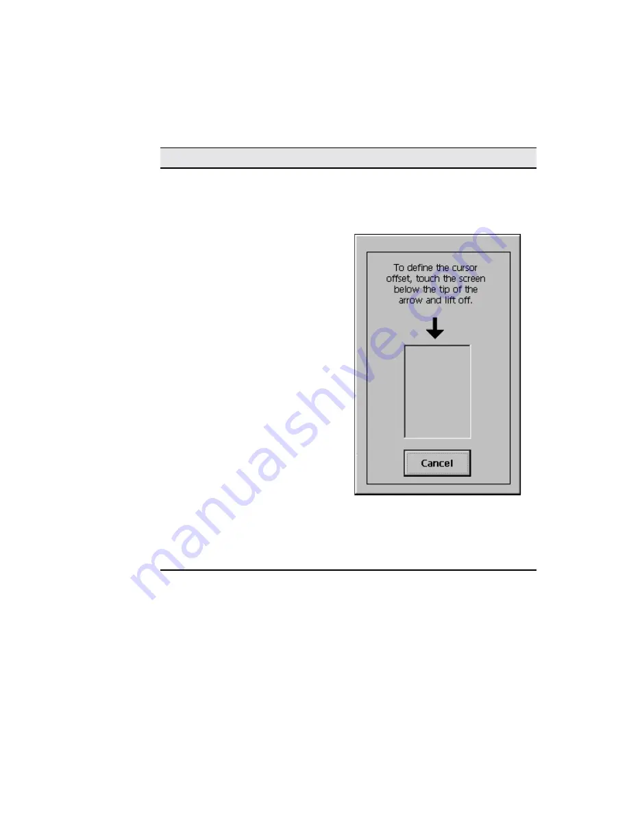
Page 44: ...22 Advanced User Interface Figure 3 5 Desktop and Keyboard Settings Dialog Box ...

Page 45: ...s 800 x 600 75Hz Supported in all terminals 800 x 600 85Hz Supported in all terminals 1024 x 768 60Hz Supported in all terminals 1024 x 768 75Hz Supported in all terminals 1024 x 768 85 Hz Supported in all terminals 1280 x 1024 60 Hz Supported in the T1010 only Color Palette drop down list box Select the color resolution for applications used with the terminal 8 bit 256 colors or 16 bit 65 536 col...

Page 46: ...he following keyboard mappings are supported by the firmware Table 3 1 Desktop and Keyboard Settings Dialog Box Continued Function Description Belgian Dutch Belgian French Brazilian ABNT Canadian Eng Multi Canadian FR Multi Canadian French Croatian Czech Danish Dutch English UK English US Finnish French German Greek Hungarian Italian Italian 142 Japanese Latin American Norwegian Polish 214 Polish ...

Page 47: ...er Setup dialog box Figure 3 6 Browser Setup Dialog Box Select whether or not to set up a local browser and click Next to the next step If you selected Yes the Browser URLs dialog box Figure 3 7 displays If you selected No the browser setup is skipped and the Local Printer Setup dialog box Figure 3 11 is displayed ...

Page 48: ...26 Advanced User Interface Figure 3 7 Browser URLs Dialog Box Type the URLs for the Home and Search pages or accept the defaults and click Next to continue ...

Page 49: ...Advanced User Interface 27 Figure 3 8 Preferences Dialog Box Select the desired preferences or accept the defaults and click Next to continue ...

Page 50: ...28 Advanced User Interface Figure 3 9 History and Favorites Dialog Box Uncheck the boxes or accept the defaults checked for the indicated selections and click Next to continue ...

Page 51: ...r Dialog Box If your terminal accesses the Internet through a proxy server check the Use proxy server box and make the required entries in the now enabled text and check boxes and click Next to continue to the Local Printer Setup dialog box Figure 3 11 ...

Page 52: ...your terminal select Yes and the dialog boxes that follow will prompt you for printer information Note This local printer setup applies only to RDP connections See Local Printers for further information If you select No the default you will skip the remaining printer dialog boxes and the Finish dialog box Figure 3 17 will display Make your selection and click on Next ...

Page 53: ...Advanced User Interface 31 Figure 3 12 Select Printer Port Dialog Box In the Select Printer Port dialog box select the port to which the printer is connected and click on Next to go to the next step ...

Page 54: ...32 Advanced User Interface Figure 3 13 Select Printer Model Dialog Box In the Select the Printer Model dialog box select the printer model from the list and click on Next to go to the next step ...

Page 55: ...Advanced User Interface 33 Figure 3 14 Printer Name Dialog Box In the Name Your Printer dialog box enter a name by which to refer to your printer and click on Next to go to the next step ...

Page 56: ... 15 Default Printer Dialog Box In the Set Default Printer dialog box select whether or not you want your Windows based programs to use this printer as the default printer Yes is the default selection Click on Next to go to the next step ...

Page 57: ... If you have another printer connected to a different port on your terminal select Yes in the Configure another printer dialog box Click on Next to go to the next step If you selected Yes the printer setup process will repeat If you selected No the Finish dialog box will open ...

Page 58: ...gure 3 17 Finish Dialog Box The Finish dialog box is informational Click on the Finish command button to apply your selections and quit the Setup Wizard After the Setup Wizard closes the Terminal Settings Change dialog box displays ...

Page 59: ...When you click on Restart the terminal will go through the boot process and restart in the normal operating mode If you want to change any of the selections after you restart press F2 to open the Terminal Properties dialog box see Changing Terminal Properties for instructions ...

Page 60: ...eets that can be invoked by clicking on their individual tabs The following 6 sheets are used to change terminal properties Network discussed in Network Configuration Upgrade beginning with Cable Firmware Upgrades Security beginning with Security Properties Web discussed in Web Browser Apps beginning with Additional Applications Devices beginning with Devices Properties Printers discussed in Local...

Page 61: ...ce Figure 4 1 Terminal Properties Dialog Box Note The amount of available RAM may differ between terminal models Resetting to Factory Defaults Proceed as follows 1 Click on the General tab of the Terminal Properties dialog box ...

Page 62: ...e If the above reset procedure fails call technical support at Compaq 800 OKCOMPAQ for instructions on using a hot key reset procedure Figure 4 2 System Settings Change Dialog Box Terminal Settings Change Dialog Box When you change terminal properties using the Setup Wizard or the Terminal Properties dialog box you will click on either the Finish or OK command button to save your new settings and ...

Page 63: ...x contains the Restart command button The terminal must be restarted in order for your new settings to take effect Click on Restart to restart the terminal The Connection Manager displays See Connections Management for detailed information about configuring and making terminal connections ...

Page 64: ...perties sheet lets you configure your network See Figure 5 1 to view this properties sheet Using the Network Properties Sheet To invoke this properties sheet 1 Press F2 to invoke the Terminal Properties dialog box 2 Click on the Network tab ...

Page 65: ...44 Advanced User Interface Figure 5 1 Network Properties Sheet The following table discusses the functions of the Network properties sheet ...

Page 66: ... a static IP address in this field Subnet Mask Enter the subnet mask of the IP address Gateway Enter the gateway of the IP address Terminal Name Enter a name of your choice for the terminal Network Speed Use this scroll list to select a network communication speed The choices are in Mb s Auto Detect default 10 Mbs Half Duplex 10 Mbs Full Duplex 100 Mbs Half Duplex 100 Mbs Full Duplex Note If you d...

Page 67: ...d button to invoke the Advanced Network Settings dialog box Enable DNS Use the controls in this group to set domain primary and secondary IP addresses for DNS The default for the group is disabled Enable DNS not checked Enable WINS Use the controls in this group to set the primary and secondary IP addresses of a WINS server The default for the group is disabled Enable WINS not checked Table 5 1 Ne...

Page 68: ...curately for cookies to work properly for some Web pages Use of a time server is preferred See SNTP Client in External Devices for information about synchronizing system time to a time server Using the Web Properties Sheet To invoke this properties sheet 1 Press F2 to invoke the Terminal Properties dialog box 2 Click on the Web tab ...

Page 69: ...48 Advanced User Interface Figure 6 1 Web Properties Sheet Table 6 1 discusses the functions of the Web properties sheet ...

Page 70: ...h engines Persistent browser cache check box Check this box if you want the contents of the browser cache to be retained between sessions Enable Favorites check box Check this box to enable the favorites table in the browser Preferences command button Opens the Preferences dialog box Figure 6 2 Make selections indicated by the prompts in this dialog box Proxy Information command button Opens the P...

Page 71: ...50 Advanced User Interface Figure 6 2 Preferences Dialog Box Figure 6 3 Proxy Information Dialog Box ...

Page 72: ...ent options See Figure 7 1 Using the Apps Properties Sheet Figure 7 1 shows this properties sheet To invoke the Apps properties sheet 1 Press F2 to invoke the Terminal Properties dialog box 2 Click on the Apps tab in the Terminal Properties dialog box Table 7 1 describes the functions of the Apps properties sheet ...

Page 73: ...es Sheet Function Description Global Settings Group box used to manage ICA sessions ICA Client Settings Click on the ICA Client Settings command button in the Global Settings group box See ICA Client Settings in the Advanced User Interface section for details about ICA client settings ...

Page 74: ...s Change DHCP Option Use this command button to invoke the Change DHCP Option IDs dialog box See DHCP Firmware Upgrades in Firmware Upgrades for details Port Lock Click on the Port Lock command button to invoke the Port Lock dialog box Use the list of check boxes in the dialog box to select which ports you want to lock enable The default is all boxes checked RDP Encryption Enable Click this check ...

Page 75: ...ough the Apps properties sheet found in the Terminal Properties dialog box See Additional Terminal Applications for detailed information about the Apps properties sheet Figure 8 1 shows the Global ICA Settings dialog box Figure 8 1 Default Hotkeys Properties Sheet Note An ICA session must be running for these hotkeys to function ...

Page 76: ...rties sheet for the Global ICA Client Settings dialog box The following figure shows the Default Hotkeys properties sheet Use the pull down scroll boxes on the Default Hotkey properties sheet to customize default hotkey key sequences The following table describes the hotkeys Table 8 1 Default Hotkeys Properties Sheet Function Description Status Dialog This function displays ICA connection status C...

Page 77: ...erences properties sheet Figure 8 2 Preferences Properties Sheet The following table describes each function of the properties sheet Alt Esc This hotkey cycles the focus through the minimized icons Alt Tab This hotkey cycles sequentially through applications that are open A window appears to display the applications as you cycle through them Alt Backtab This hotkey cycles sequentially through appl...

Page 78: ...ow Colors Two or three radio buttons are displayed If the terminal Color Palette using the Display properties sheet in the Terminal Properties dialog box is 256 colors radio buttons for 16 or 256 colors are displayed If 65536 is selected in the Color Palette after restarting the terminal an additional radio button Thousands is displayed Note The ICA server must be capable of supporting 16 bit colo...

Page 79: ...uely identify resources such as mapped printers associated with a given client device The client name should be unique for each computer running a copy of a Citrix ICA Client If you do not use unique client names device mapping and application publishing may not operate correctly The default is WBT mac address The maximum length of the client name is 15 characters Allow Automatic Client Updates ch...

Page 80: ...erver group If you checked use HTTP server location you must enter the server address and port to use Delete Use this button to delete the name or IP address of a server from the selected group use HTTP server location Check this box if your firewall restricts UDP broadcasts This option enables the client to retrieve a list of all Citrix servers on the network and a list of all published applicati...

Page 81: ...properties sheet displays The following figure shows this sheet Figure 8 4 Firewall Settings Properties Sheet The following table describes each of the functions of this sheet Server Group Use this drop down list to select whether the servers entered in the Address List field belong to your Primary first backup Backup 1 or second backup Backup 2 group Rename Group Opens the Rename Server Location ...

Page 82: ... Proxy Check this box to enable a SOCKS proxy connection SOCKS is a protocol that sets up a proxy server between a client and a server This proxy server then acts as a channel for communication between the client and server By default the box is not checked Address of Proxy to Use Enter in this text box the address of the proxy server By default this box is deactivated Port Enter in this text box ...

Page 83: ...ation of the differences between the methods of accessing published applications via the NFuse server and limitations on the NFuse server application setup for use with Model T10x0 series terminals Note PNLite connections are not supported by failover See Failover To invoke this properties sheet 1 Click on the ICA Client Settings command button on the Apps properties sheet 2 Click the PNLite tab T...

Page 84: ...Enable PNLite Check to enable the PNLite application Server area Enter the address and port number of the NFuse server in the Address and port of NFuse server text boxes User credentials area Enter the requested information in the User Name Password and Domain text boxes Check the Save password box if you want the password retained on the terminal ...

Page 85: ...l Up Dialing Properties and Configuration 18 Dial Up TCP IP Settings and Security 19 Dial Up Scripts 20 RDP Connections 21 Terminal Emulation Connections 22 TCP IP Telnet Configuration 23 Internet Explorer Connections 24 Editing ICA Connections 25 Editing RDP Dial Up and Terminal Emulation Connections ...

Page 86: ... on the Configure tab in the Connection Manager dialog box 2 Click on the Add command button on the Configure properties sheet See Connection Configuration for details about the Connection Manager Use the scroll list shown in the dialog box above to select the type of connection protocol you want When you choose from the list above you are deciding which connection protocol you want to use to conn...

Page 87: ...on Dial Up Client Connects using a modem and PPP Point to Point Protocol See Dial Up Connections for further instructions about how to create this kind of connection Microsoft Remote Desktop Client RDP Remote Desktop Protocol which connects to a WTS Windows Terminal Server server See RDP Connections for further instructions about how to create this kind of connection Internet Explorer Local browse...

Page 88: ... Also un check the box for CDS printing Using the Startup Function Your terminal can be set to automatically connect to a server when you turn your terminal on This function is set using the Connection Startup dialog box The following figure shows this dialog box Click on one of the two radio buttons in the Startup Options group box in the Connection Startup dialog box above to select a start up o...

Page 89: ...Connection Click this radio button to use the connection you selected in the Connection Manager as the default connection The default connection is the connection that always appears in the Connection Name list Automatically Start the Selected Connection at Startup Click this radio button to start the connection you selected in the Connection Manager automatically at startup Note Autostart status ...

Page 90: ...ist to select Citrix ICA Client 2 Click on OK Figure 10 1 shows the Specify Connection Type dialog box This is the first dialog box that appears in the series Network Connection Click on this radio button to create a network ICA connection This type of connection requires a direct line to the network such as 10Base T See Network Connections Dial In Connection Click on this radio button to create a...

Page 91: ...g Box Network Connections Select Network Connection then click on the Next button A Citrix search message displays Figure 10 2 Citrix Search Message If the connection is found the following sequence of dialog boxes displays Use them to set up your network ICA connection ...

Page 92: ...r or Published Application 2 Select a server or an application from the drop down scroll list or type the information in the text entry box Note The Refresh command button refreshes the drop down scroll list Note The Server Location command button invokes the Server Location dialog box The server in Server Location will act as a master browser for creation of the Address list See Figure 10 4 ...

Page 93: ...ver name or IP address click on the Add command button to invoke the Add Server Address dialog box Figure 10 5 Add Server Address Dialog Box 4 Enter the name or IP address of the Citrix server Click on OK in this dialog box and then click on OK in the Server Location dialog box 5 Click on Next ...

Page 94: ...a connection in the text box in the Select a Title for the ICA Connection dialog box then click on Finish Figure 10 7 Specify an Application Dialog Box To use the Specify an Application dialog box 1 Enter the command line and directory of the application that you intend to invoke 2 Click on Next ...

Page 95: ...10 8 Specify Logon Information Dialog Box To use the Specify Logon Information dialog box 1 If needed enter a user name a password and a domain for connecting to an application 2 Click on Next Figure 10 9 Select Window Options Dialog Box ...

Page 96: ...Note The ICA server must be capable of supporting 16 bit color for the Thousands selection to work If not the terminal will display only 256 8 bit colors when Thousands is selected 2 Click on Next Figure 10 10 Compression Encryption and Sound Dialog Box To use the Compression Encryption and Sound dialog box 1 Enable or disable the following functions a Use Printer Configuration Utility check box S...

Page 97: ...for mouse clicks to show that the user s input is being processed d Encryption Level Drop down menu allows selection of the encryption level Basic default RC5 128 bit Login Only RC5 40 bit RC5 56 bit RC5 128 bit 2 Click on Next Figure 10 11 Firewall Settings Dialog Box 1 Enable or disable the following functions a Use Alternate Address Through Firewalls b SOCKS c Connect Via SOCKS Proxy d Address ...

Page 98: ... following a A modem connection such as Hayes Compatible on Com1 b A serial connection such as Serial Cable on Com1 2 Enter the area code the phone number and the country code in the appropriate fields 3 Click on Configure to use the Device Properties dialog box See Using the Device Properties Dialog box for information on the Device Properties dialog box 4 See Figure 10 6 through Figure 10 11 and...

Page 99: ...nnection dialog box see Creating New Connections 1 Use the drop down scroll list to select Dial Up Client 2 Click on OK Following are the three dialog boxes that display in succession during a dial up configuration process When you are finished with the configuration the new connection will be added to the Connection Name list in the Connection Manager See Figure 11 1 to view the first dialog box ...

Page 100: ...82 Connection Configuration Figure 11 1 Dial Up Configuration Wizard 1 To use the first dialog box 1 Enter a name for your dial up connection a maximum of 20 characters but not 2 Click on Next ...

Page 101: ... as Serial Cable on Com1 2 Enter your information in the pertinent fields Country Code and Area Code will activate if Use Country Code and Area Code is enabled 3 Click on the Dialing Properties command button to open the Dialing Properties dialog box See Using the Dialing Properties Dialog Box for details about this dialog box 4 Click on the Configure command button to open the Device Properties d...

Page 102: ...d Security for details about this dialog box 7 Check the Enable RAS Script check box and click on the Script command button to open the RAS Script dialog box See Dial Up Scripts for details about this dialog box 8 Click on Next This opens the dialog box shown in Figure 11 3 To use the dialog box 1 Enter your information in the pertinent fields If you do not know the information contact your system...

Page 103: ...Connection Configuration 85 Figure 11 3 Dial Up Configuration Wizard 3 ...

Page 104: ...e set using the Dialing Properties dialog box Figure 12 1 Device properties are set using the Device Properties dialog box Figure 12 2 Note See Null Modem Cable Pin Assignments for a suggested null modem cable for use with your terminal Using the Dialing Properties Dialog Box Use the Dialing Properties dialog box to set the dialing properties for your dial up connection See Dial Up Connections to ...

Page 105: ...88 Connection Configuration Figure 12 1 Dialing Properties Dialog Box The following table discusses the functions of the dialog box ...

Page 106: ...de Enter the local country code of the country to which you are dialing The default for this field is 1 Note Refer to a phone directory for country codes Disable Call Waiting by Dialing 1 Click on the check box 2 Select from the drop down scroll list one of the following 70 default 70 1170 Tone Dialing Click on this radio button to enable tone dialing Tone Dialing is the default Pulse Dialing Clic...

Page 107: ... set your modem s dialing patterns Local Calls Dialing Enter the local call dialing pattern The default is 9 G Local Long Distance Calls Dialing Enter the long distance call dialing pattern The default is 9 1FG International Calls Dialing Enter the international call dialing pattern The default is 9 011 EFG Note An explanation of the lettering scheme for dialing patterns is located below the funct...

Page 108: ... default of the Device Properties dialog box The following table discusses the functions of this properties sheet Table 12 2 Port Settings Properties Sheet Function Description Manual Dial Click on this check box to set up for manual dialing Terminals Use this group box to record terminal windowing information Use Terminal Window Before Dialing Use Terminal Window After Dialing Connection Preferen...

Page 109: ...ll parameters Cancel the Call if Not Connected Within 1 Enter in this field the number of seconds to wait before a call is canceled The default is 120 with the function enabled 2 Click the check box to enable the function Wait for Dial Tone Before Dialing Click on the check box to enable the function By default this function is enabled Wait for Credit Card Tone Enter in the field the period in sec...

Page 110: ...vers TCP IP settings and dial up security Using the TCP IP Settings Dialog Box Click on the TCP IP Settings command button in the second dialog box of the Dial Up Configuration Wizard to set TCP IP dial up settings When this command button is pressed the TCP IP Settings dialog box displays Figure 13 1 shows this dialog box Figure 13 1 TCP IP Settings Dialog Box ...

Page 111: ...d enabled Use IP Header Compression Click on this check box to enable Use IP Header Compression By default this function is activated and enabled Use SLIP Click on this check box to enable this function SLIP is Serial Line Internet Protocol By default this function is not enabled Use Assigned IP Address Click here to activate this text box By default the text entry box is not activated Use Server ...

Page 112: ...minal to accept any authentication including clear text Authentication determines whether a request originated from the correct user or application Accept Only Encrypted Authentication Click on this radio button to set your terminal to accept only encrypted authentication Encryption is a method of hiding data that is transmitted across a network Accept Only Microsoft Encrypted Authentication Click...

Page 113: ...anel of the Dial Up Configuration Wizard These dialog boxes automate actions that otherwise would be performed in text mode after dialing The Script Name dialog box Figure 14 1 enables you to create a script under a new name edit an existing script or delete an existing script Press the New button to open the New Script Name dialog box Figure 14 2 Type the script name and press OK This opens the R...

Page 114: ...98 Connection Configuration Figure 14 1 Script Name Dialog Box Figure 14 2 New Script Name Dialog Box ...

Page 115: ...isplays the name of the currently selected script You may change the selection by clicking on the Change button to open the Script Name dialog box Select another script and click OK Script area Text Box Lists the script input output strings Wait For Displays strings received from the host Respond With Displays what the terminal sends in response to the Wait For string ...

Page 116: ...create a new line in the script or edit an existing selected line The specific scripts are unique to each target system Up Down Delete buttons Use Up and Down to move a selected line in the script up or down in the list To delete a line select it and press Delete You will be prompted to confirm deletion of the line Table 14 1 RAS Script Dialog Box Continued Function Description ...

Page 117: ...ialog box is open see Creating New Connections 1 Use the drop down scroll list to select Microsoft Remote Desktop Client 2 Click on OK Following are the four dialog boxes that display in succession during the configuration process When you are finished with the wizard the new connection will be added to the Connection Name list in the Connection Manager Figure 15 1 shows the first dialog box of th...

Page 118: ... 15 1 WTS Connection Wizard 1 To use the first dialog box 1 Enter a name for your dial up connection in Name 2 Enter the name or IP address of the server in Server 3 Check the Low Speed Connection check box if appropriate 4 Click on Next ...

Page 119: ...iguration 103 Figure 15 2 WTS Connection Wizard 2 To use the second dialog box 1 Check the Automatic Logon check box if appropriate 2 Enter a user name password and a domain to complete the information 3 Click on Next ...

Page 120: ...d dialog box in the wizard 1 Click on either the Desktop or Application File Name radio buttons 2 If you clicked on Desktop click on Next 3 If you clicked on Application File Name a Enter the name of the application b Enter the name of the directory where it resides c Click on Next ...

Page 121: ...Connection Configuration 105 Figure 15 4 WTS Connection Wizard 4 To use the fourth dialog box click on Finish The Connection Manager displays listing your new RDP connection ...

Page 122: ...New Connections 1 Use the drop down scroll list to select Terminal Emulation 2 Click on OK Following are the three dialog boxes of this wizard When you are finished configuring a connection the new connection will be added to the Connection Name list in the Connection Manager Figure 16 1 shows the first dialog box of this wizard ...

Page 123: ...st 3 Select the terminal type from the VT TerminalID scroll list Table 16 1 describes the available functions in the VT TerminalID scroll list 4 Click on Next to continue to the Host Information dialog box Figure 16 3 Note Depending on the emulation chosen the appearance of the TE Client Connection Wizard Connection Information dialog box changes to provide for selecting appropriate parameters for...

Page 124: ...ault 31 Select Emulation IBM3270 1 Then select from IBM 3270 Model 3278 2 3278 3 3278 4 3278 5 3278 2 E default 3278 3 E 3278 4 E 3278 5 E 3279 2 3279 3 3279 4 3279 5 or 3287 1 2 Check the Right Ctrl Acts as Enter Key or the Left Ctrl Acts as Reset Key check boxes if you want these functions enabled for 3270 emulation Select Emulation IBM5250 1 Select from IBM 5250 Model 5291 1 5292 2 5251 11 3179...

Page 125: ...tional Settings Opens the International Settings dialog box see Figure 16 2 The particular controls and selections that appear in this dialog box depends on the terminal emulation selected Make keyboard character set and other selections in this dialog box as applicable Table 16 1 Terminal Emulation and Terminal Type Continued Terminal Emulation Terminal Type ...

Page 126: ...and button if appropriate See Using the TCP IP Telnet Configuration Dialog Box for information about the Advanced command button c Click on Next The Automate Login Process dialog box displays See Figure 16 4 and proceed with these instructions 3 If you clicked on Modem a Select a configuration from Configuration Name b Use the Configure command button if appropriate See Using the Modem Settings Di...

Page 127: ...Com1 or Com2 Dialog Box for information about the Configure command button c Click on Next The Automate Login Process dialog box displays See Figure 16 4 and proceed with these instructions Figure 16 4 TE Client Connection Wizard Automate Login Process To use the Automate Login Process dialog box 1 Fill in the Parameters group box as appropriate using the following functions a Set Initiation Strin...

Page 128: ...script from the Script scroll list as appropriate 5 Click on Next to open the Printer Port Settings dialog box Figure 16 5 TE Client Connection Wizard Printer Port Settings To use the Printer Port Settings dialog box 1 Check the Use Network Printer box if you want to print from a printer in your network Checking this box enables LPD Hostname text box and the FormFeed Terminator Translate National ...

Page 129: ... of COM1 or COM2 dialog box For details about the available selections in this dialog box see Using the Configuration of Serial Cable on Com1 or Com2 Dialog Box 3 Click on Next This will open the GUI Overrides dialog box Figure 16 6 TE Client Connection Wizard GUI Overrides To use the GUI Overrides dialog box 1 Select the appropriate functions from Command Bar Items list box Command bar items are ...

Page 130: ...Close These functions are actions that will take place when the terminal emulation session is closed 3 Click on the Disable Status Bar or No Connection Warning on Close check boxes as appropriate Disable Status Bar deactivates the status bar in a terminal emulation session and No Connection Warning on Close deactivates any kind of warning before a session closes Click on Finish The Connection Mana...

Page 131: ...ation connection only Using the TCP IP Telnet Configuration Dialog Box The Advanced command button on the TE Client Connection Wizard Host Information dialog box invokes the TCP IP Telnet Configuration dialog box Figure 17 1 shows this dialog box Figure 17 1 TCP IP Telnet Configuration Dialog Box ...

Page 132: ... uses to talk to the host The default is 0 Telnet Name Enter the Telnet virtual terminal name The default depends on emulation VT400 7 bit default is vt420 Suppress Use the functions of this group box as needed controls in this area become active depending on the type of emulation selected Echo default 3270 Regime TN3270E TN5250E Force Negotiation Use the Binary and EOR drop down scroll lists to c...

Page 133: ...ns 3270 LU Device Name This group box is used to identify the LU Logical Unit TN3270E Options This group box is used to set TN3270E options The options are Bind BIND Berkeley Internet Name Domain DNS server Responses System response SysReq System requests Note Associate LU1 Printer and LU3 Printer are deactivated Table 17 1 TCP IP Telnet Configuration Continued Function Description ...

Page 134: ...is pressed Use this dialog box to set up 5250 options The options are Device Name Name of the device assigned to a Telnet session User Password Library and Menu Initial entries on a standard startup screen Program Name of the initial program Note All entries are 10 characters or less Table 17 1 TCP IP Telnet Configuration Continued Function Description ...

Page 135: ...rom the drop down scroll list Configure Opens the Device Properties dialog box See Using the Device Properties Dialog Box for information about this function Area Code Enter the area code in this text box Telephone Number Enter the telephone number in this text box Country Code Enter the country code in this text box Dialing From This field automatically lists where you are calling from Dialing Pr...

Page 136: ...n of Serial Cable on Com1 or Com2 Dialog Box This dialog box opens when the Configure command button is pressed for a serial connection type selection Figure 17 3 shows this dialog box Figure 17 3 Configuration of Serial Cable on Com1 or Com2 Dialog Box ...

Page 137: ...ud Rate Parity Flow Control Data Bits Stop Bits Transmit Limit Each is presented as a drop down scroll list Click on the upper right down arrow to display the list and select a value The defaults are listed consecutive to the Function list to the left as follows 9600 None Input 8 1 Unlimited Local Echo Check this check box if you want transmitted characters to appear on the dialup terminal window ...

Page 138: ...is open see Creating New Connections 1 Use the drop down scroll list to select Internet Explorer 2 Click on OK This opens the Internet Explorer Setup dialog box Figure 18 1 3 Type a Title for the connection 4 Enter the URLs of your choice for the Start and Search pages 5 If this server is to be included in failover check the Allow to ping Start Site check box Note To help decide whether you should...

Page 139: ...n is to an NFuse server that provides ICA links within a Web page to allow ICA sessions to be launched from within a browser window refer to NFuse Server Configuration Requirements for information concerning limitations on the NFuse server application setup for use with Model T10x0 series terminals ...

Page 140: ...ons The Connection Manager lets you edit individual ICA connection parameters It is done through the Edit Connection Details dialog box The following figure shows this dialog box Figure 19 1 Edit Connection Details Dialog Box ...

Page 141: ...Properties Sheet The Server properties sheet is displayed by default for the dialog box Table 19 1 describes the functions of the Server properties sheet Table 19 1 Server Properties Sheet Function Description Select a Citrix Server From the List or Type in a server Name Click on Citrix Server Enable this radio button to connect to a Citrix server Published Application Enable this radio button to ...

Page 142: ...rver up the list 1 Select a server to move up 2 Click on the Move Up command button Move Down Click on this command button to move a server down the list 1 Select a server to move down 2 Click on the Move Down command button Address Lists the servers Default List Lists the default servers Network Protocol Lists the network protocol used by the server Table 19 1 Server Properties Sheet Continued Fu...

Page 143: ...cation Properties Sheet Invoke the properties sheet by clicking on the Application tab Table 19 2 describes the functions of the properties sheet Table 19 2 Application Properties Sheet Function Description Command Line Enter the command line used to invoke the application Working Directory Enter the directory where the application is stored ...

Page 144: ...es Sheet Invoke the properties sheet by clicking on the Logon tab Table 19 3 describes the functions of the Logon properties sheet Table 19 3 Logon Properties Sheet Function Description Username Enter the user name used to log into the server Password Enter the password used to log into the server Domain Enter the domain name of the server ...

Page 145: ...132 Connection Configuration Using the Window Properties Sheet The Window properties sheet is shown in the following figure Figure 19 4 Window Properties Sheet ...

Page 146: ...radio buttons for 16 or 256 colors are displayed If 65536 is selected in the Color Palette after restarting the terminal an additional radio button Thousands is displayed Note The ICA server must be capable of supporting 16 bit color for the Thousands selection to work If not the terminal will display only 256 8 bit colors when Thousands is selected When using a PPP connection 16 color mode may pr...

Page 147: ...Table 19 5 Options Properties Sheet Function Description Use Printer Configuration Utility Check this box default to allow creation of a new printer in the ICA Client Printer dialog box on the ICA server Uncheck to use Windows to add a printer Compress Data Stream Check this check box to enable compressed data streaming By default the box is checked Enable Sound Check this check box to enable soun...

Page 148: ...dth consumption and total packets transmitted resulting in reduced latency and consistent performance regardless of the network connection SpeedScreen is not available when connecting to MetaFrame for UNIX 1 0 and 1 1 servers Encryption Level Select from Basic 8 bit default 40 40 bit 56 56 128 128 128 bit Logon Table 19 5 Options Properties Sheet Continued Function Description ...

Page 149: ...ing the Title Properties Sheet The Title properties sheet is shown in Figure 19 6 Figure 19 6 Title Properties Sheet This properties sheet contains only one function Enter the title of your ICA connection in the text box on the sheet ...

Page 150: ...ies Sheet Function Description Use Alternate Address Through Firewalls Click on this check box to enable the function By default the box is unchecked SOCKS SOCKS Socket Secure is networking proxy protocol It enables hosts on one side of a SOCKS server to gain access to hosts on the other side of the SOCKS server The SOCKS server authenticates and authorizes the requests establishes a proxy connect...

Page 151: ...y server Activate this box by clicking on Connect Via SOCKS Proxy By default this box is deactivated Port Enter the port number to connect to Activate this box by clicking on Connect Via SOCKS Proxy By default this box is deactivated Table 19 6 Firewall Settings Properties Sheet Continued Function Description ...

Page 152: ...d button To edit a dial up connection you invoke the Dial Up Configuration Wizard See Dial Up Connections for detailed information about using this wizard To edit terminal emulation you invoke the TE Client Connection Properties dialog box See Terminal Emulation Connections for detailed information RDP Connections The Connection Manager lets you edit individual RDP connection parameters It is done...

Page 153: ... properties sheets Depending on your connections configuration you use one of these properties sheets to edit connection parameters To invoke the dialog box 1 Click on the Configure tab in the Connection Manager dialog box 1 Click on an RDP connection in the Connections Name list 2 Click on the Edit command button on the Configure properties sheet ...

Page 154: ...nal Connection Manager Use the following functions to change the connection s network parameters Name Enter the name of the connection in this field When OK is selected your changes will be saved and Name will replace what was selected Server Enter the address of the server in this field Automatic Logon Click on this check box to enable automatic logon for your terminal Enabling this function enab...

Page 155: ...by clicking on the Application tab in the Edit Connection dialog box Use this properties sheet to reconfigure the applications related portion of the connection Figure 20 2 shows this sheet Figure 20 2 Application Properties Sheet The following table describes the functions of the Application properties sheet ...

Page 156: ...owing functions to specify an application to run when the connection is made Desktop Click on this radio button to open the desktop when the connection is made When selected the File Name and Working Directory text boxes are disabled File Name Click on this radio button and in the associated text box enter the full path name of an application that will run Working Directory Enter the path to the w...

Page 157: ... Add On 29 Aironet Wireless LAN Adapter Setup 30 PC Card Adapters for Modems 31 Touchscreens 32 Date Time Properties 33 JETCET PRINT 34 Local Printers 35 PC Card Adapters for Token Ring Networks 36 SNTP Client 37 PC Card Adapters for Wireless Networks 38 Volume Properties ...

Page 158: ... SE models and LE models respectively To open the Devices properties sheet 1 Press F2 to open the Terminal Properties dialog box 2 Click on the Devices tab in the Terminal Properties dialog box Devices Properties Sheet Table 21 1 describes the functions of this properties sheet ...

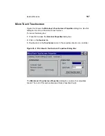
Page 159: ...148 External Devices Figure 21 1 Devices Properties Sheet ...

Page 160: ...ee Managing Network Adapters in External Devices Add on Click on this icon to invoke the Add on dialog box For detailed information see Add on in External Devices Aironet Click on this icon to invoke the Aironet Wireless Lan Adapter Setup dialog box For detailed information see Aironet Wireless Land Adapter in External Devices Date Time Click on this icon to invoke the Date Time Properties dialog ...

Page 161: ...evices Touchscreen Click on this icon to invoke the MicroTouch Touchscreen Properties dialog box For detailed information see Touchscreens in External Devices Volume Click on this icon to invoke the Volume Properties sheet For detailed information see Volume Properties Sheet in External Devices WaveLAN Click on this icon to invoke the WaveLAN IEEE Settings dialog box For detailed information see P...

Page 162: ... is a device that physically connects a terminal to a network The Adapters Configuration dialog box gives you the ability to configure the adapters on a terminal Figure 22 1 shows the dialog box Figure 22 1 Adapters Configuration Dialog Box ...

Page 163: ...inal to verify terminal connection to the network upon boot a message is displayed if the test fails If you are using an adapter that does not immediately connect to the network upon boot you may desire to un check the box so that the message does not appear each time the terminal boots Accept Terminal Name from DHCP check box Some but not all DHCP servers can assign a terminal name through DHCP o...

Page 164: ...erties Sheet Function Description Obtain an IP Address via DHCP Click on this radio button to let the terminal obtain an IP address automatically using DHCP This button is selected by default Specify an IP Address Click on this radio button to enter an IP address subnet and gateway By default this function is disabled IP Address Enter an IP address in this field By default this text box is blank S...

Page 165: ...ties sheet Table 22 3 Name Server Properties Sheet Function Description Primary DNS Enter the IP address of your primary DNS Domain Name Service server By default this text box is blank Secondary DNS Enter the IP address of your secondary DNS server By default this text box is blank Primary WINS Enter the IP address of your primary WINS Windows Internet Naming Service server By default this text b...

Page 166: ...ab 3 Click on the Add on icon in the icon container on the Devices properties sheet Note To install an add on refer to the specific add on documentation Add on Dialog Box Uninstall Tab Figure 23 1 shows the Uninstall tab section of the Add on dialog box To remove a specific firmware add on select it from the list and click Remove Follow the prompts to complete the removal process The terminal must...

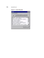
Page 167: ...156 External Devices Figure 23 1 Uninstall Dialog Box ...

Page 168: ...vices 157 Add on Dialog Box System Tab Figure 23 2 shows the System tab section of the Add on dialog box It displays information about available flash memory and has no user controls Figure 23 2 System Dialog Box ...

Page 169: ...ronet wireless LAN adapter solely by menu selections To open this dialog box 1 Press F2 to open the Terminal Properties dialog box 2 Click on the Devices tab 3 Double click on the Aironet icon in the icon container on the Devices properties sheet Figure 24 1 Aironet Wireless LAN Adapter Setup Dialog Box ...

Page 170: ...vices Using the Aironet Dialog Box To configure the wireless LAN adapter select a property from the Property list and select the desired value from the Value drop down menu Repeat the process for each listed property ...

Page 171: ... PCMCIA modems Figure 25 1 shows the Add or Change Modem dialog box Use this dialog box to set up a PCMCIA modem To open the dialog box click on the Add Change Modem command button on the Devices properties sheet Figure 25 1 Add or Change Modem Dialog Box Table 25 1 discusses the functions of this dialog box ...

Page 172: ...em Init Commands Enter a modem initialization command string in this field The default is ATE0V1 C1 D1 cr Flow Settings Use this group box to set the following flow settings Flow Hardware Enter a flow hardware command string in this field The default is AT K3 cr Flow Software Enter a flow software command string in this field The default is AT K4 cr Flow Off Enter a flow hardware command string in...

Page 173: ... not know this information ask your system administrator Figure 25 2 shows the dialog box To invoke the dialog box click on the ISDN Settings command button on the Devices properties sheet Note These settings are specific to EiCon Tech modems only Figure 25 2 ISDN Settings Dialog Box Table 25 2 discusses the functions of the ISDN Settings dialog box ...

Page 174: ... switch type The default is North America Service Profile ID 1 Use this field to enter Service Profile ID 1 Only numbers are allowed in this text box Note Enter the SPID provided by your ISDN line provider telephone company Service Profile ID 2 Use this field to enter Service Profile ID 2 Only numbers are allowed in this text box Note Enter the SPID provided by your ISDN line provider telephone co...

Page 175: ...en Figure 26 1 shows the ELO Touchscreen dialog box Use this dialog box to calibrate an ELO touchscreen To open this dialog box 1 Press F2 to open the Terminal Properties dialog box 2 Click on the Devices tab 3 Double click on the ELO Touch icon in the properties sheet s icon container Figure 26 1 ELO Touchscreen Dialog Box Table 26 1 discusses the dialog box ...

Page 176: ...on will be deactivated if a touchscreen is not connected to one of the terminal s Com ports or USB connectors Note After a Com port is selected the terminal must be restarted When you click on Calibrate a white screen with a single cross hair in the upper left hand corner displays 1 Touch the cross hair The cross hair will move to the lower right hand corner 2 Touch the cross hair The cross hair w...

Page 177: ...e this dialog box 1 Press F2 to invoke the Terminal Properties dialog box 2 Click on the Devices tab 3 Double click on the Touchscreen icon in the properties sheet s icon container Figure 26 2 Microtouch Touchscreen Properties Dialog Box The Microtouch Touchscreen Properties dialog box contains four properties sheets The rest of this section discusses these properties sheets ...

Page 178: ...n Find Touchscreen see below Controller Type This field shows the controller type Firmware Version This field shows the firmware version Status This field shows the status OK Not Found If there is no MicroTouch touch screen connected to the terminal the Status field will display Not Found Connection Use this group box to configure the connection between the terminal and the touchscreen Port Select...

Page 179: ... Table 26 3 discusses the Cursor properties sheet Table 26 3 Cursor Properties Sheet Function Description Cursor Offset Use this properties sheet to set the distance between your finger and the cursor Vertical Check this check box to set the vertical distance Horizontal Edge Adjust Check this check box to set the horizontal distance ...

Page 180: ...command button to invoke a dialog box that will allow you to set distances Follow the instructions on the dialog box Stabilize Cursor This command button is always deactivated Table 26 3 Cursor Properties Sheet Continued Function Description ...

Page 181: ...tion Touch Mode Use this group box to configure a touch mode A touch mode specifies actions that equate to mouse click double click and drag events Desktop Check this check box to enable desktop mode Desktop mode is used for general desktop applications Drawing Check this check box to enable drawing mode Drawing mode is used for graphics applications Button Check this check box to enable button mo...

Page 182: ...Click on the Calibrate command button to begin the calibration process A white screen with a single cross hair in the lower left hand corner displays 1 Touch the cross hair The cross hair will move to the upper right hand corner 2 Touch the cross hair The Calibration Complete dialog box displays 3 Follow the instructions in the Calibration Complete dialog box to complete the calibration process ...

Page 183: ...ox 1 Press F2 to open the Terminal Properties dialog box 2 Click on the Devices tab 3 Double click on the Date Time on icon in the icon container on the Devices properties sheet Figure 27 1 Date Time Properties Dialog Box Use the calendar to set the date Select the Time Zone and check the check box if daylight savings time is currently in effect ...

Page 184: ...nal time will automatically synchronize to the time provided by the server Otherwise the time must be set manually To manually set the time enter a time slightly ahead of the actual time in Current Time text box and then just as the actual time reaches the set time click on the Apply button ...

Page 185: ...he JETCET printer driver The JETCET PRINT Professional dialog box Figure 28 1 allows you to select printing properties To open this dialog box 1 Press F2 to open the Terminal Properties dialog box 2 Click on the Devices tab 3 Click on the JETCET PRINT Pro icon in the Devices tab Table 28 1 describes the available printing options and settings Figure 28 1 JETCET PRINT Professional Dialog Box ...

Page 186: ...cketJetII PostScript Note These are the only supported printers Serial Handshaking drop down list box Allows selection of software or hardware handshaking between the terminal and the printer Default is software Spooler area Controls in this area are used to select print spooler options Checking Use Spooler default is checked enables the Hold Jobs check box and the spooler memory selection radio b...

Page 187: ... open when printing Properties command button Opens the Printer Properties dialog box This dialog box has four tab sections each of which contains controls for setting a category of print properties Color Figure 28 2 Dithering Figure 28 3 Toner Saver Figure 28 4 Layout Figure 28 5 Table 28 1 JETCET PRINT Professional Dialog Box Settings Continued Function Description ...

Page 188: ...178 External Devices Figure 28 3 Printer Properties Dialog Box Dithering Tab Figure 28 4 Printer Properties Dialog Box Toner Saver Tab ...

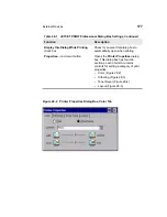
Page 189: ...External Devices 179 Figure 28 5 Printer Properties Dialog Box Layout Tab ...

Page 190: ...er Daemon LPD printing and printing from applications LPD Printing This paragraph discusses the configuration of local printing using the LPD Config dialog box Note LPD can only be used with the parallel port of a terminal Figure 29 1 LPD Config Dialog Box ...

Page 191: ...t Figure 29 2 shows the Printers properties sheet To invoke this properties sheet 1 Press F2 to invoke the Terminal Properties dialog box 2 Click on the Printers tab Table 29 1 LPD Config Dialog Box Function Description Enable Printer Check this check box to enable LPD printing to a printer connected to your terminal Printer Name Type in this field the name of the connected printer The default for...

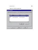
Page 192: ...External Devices 183 Figure 29 2 Printers Properties Sheet ...

Page 193: ...see Figure 29 3 which allows you to configure a printer for the port Double clicking the listing has the same effect as pressing the button Add Properties command button If the selected port does not have a printer associated with it the command button label will be Add otherwise the label will be Properties Clicking on the button opens the Printer Properties dialog box which enables the user to e...

Page 194: ... The Printer Name text box will initially contain the manufacturer s name for the printer Overtype this with the name by which you will refer to this printer If you want this to be the default printer check the Make this the default printer box this will de select another printer previously selected as default Click OK to accept the properties and close the box or click Cancel to cancel the select...

Page 195: ... RACORE token ring card Figure 30 1 shows the RACORE Token Ring Adapter Settings dialog box Use this dialog box to configure a RACORE token ring card Using the RACORE Token Ring Adapter Settings Dialog Box To invoke this dialog box 1 Press F2 to invoke the Terminal Properties dialog box 2 Click on the Devices tab 3 Click on the RACORE TR icon in the icon container on the Devices properties sheet ...

Page 196: ...his text field to enter the MAC address of the token ring PC card The default is 000000000000 Token Ring Speed Use this group box to select the speed of your token ring network The default is 16 Megabits Second 4 Megabits Second Click on this radio button if your network is set to a passing speed of 4 megabits 16 Megabits Second Click on this radio button if your network is set to a passing speed ...

Page 197: ...log box to select the SNTP server and to synchronize the terminal time Note SNTP client is available only when IE4 is installed Using the SNTP Client Dialog Box To invoke this dialog box 1 Press F2 to invoke the Terminal Properties dialog box 2 Click on the Devices tab 3 Click on the SNTP Client icon in the icon container on the Devices properties sheet Figure 31 1 SNTP Client Dialog Box ...

Page 198: ... add to the SNTP server list or edit a current selection The IP address or DNS name of the server may be used Remove deletes the selected entry from the list Synchronize Time on Boot check box Check this box if you want the terminal to automatically synchronize to the SNTP time server when the terminal boots Default is checked Synchronize command button Causes the terminal time to immediately sync...

Page 199: ...N IEEE Settings Dialog Box To invoke this dialog box 1 Press F2 to invoke the Terminal Properties dialog box 2 Click on the Devices tab 3 Double click on the WaveLAN icon in the icon container The WaveLAN IEEE Settings dialog box contains four properties sheets The rest of this section discusses these properties sheets Basic Properties Sheet The Basic properties sheet is the default of the dialog ...

Page 200: ...ou want to connect to This field must match the name of the current wireless network infrastructure The default for this field is blank Ad Hoc Demo Mode Click here to enable Ad hoc Demo Mode Enabling this mode will allow the terminal to connect to a small wireless workgroup In this mode the terminal will Ignore WaveLAN Network Name Ignore WavePOINT ll access points Fix the radio to operate at fact...

Page 201: ...r normal network use Figure 32 2 Advanced Properties Sheet The following table discusses this properties sheet Table 32 2 Advanced Properties Sheet Function Description MAC Address Enter in this field a user assigned MAC address You will not have to change this parameter for most networks You will only have to assign an address if your network uses local MAC addressing By default this field is bla...

Page 202: ...points The default is Low Density Transmit Rate Select in this scroll box the transmission rate of the connection The values are Low Standard Medium High The default is High Fixed Click to check this box to disable the Auto Transmit Rate Select function The default is unchecked Medium Reservation Select from this scroll list Off Hidden Stations This function improves wireless performance in a netw...

Page 203: ...is box to enable power management Power management conserves the life of the battery of a portable device When Card Power Management is enabled the other functions of the properties sheet are activated By default the box is unchecked Receive All Multicasts Click to check this box to enable the terminal to wake up and receive multicasts The default for this box is deactivated Maximum Sleep Duration...

Page 204: ...heet Table 32 4 discusses the properties sheet Table 32 4 Encryption Properties Sheet Function Description Enable Encryption check box Check this box to enable encryption Encryption Key text boxes Store encryption keys that you may use Encryption Data Transmission using list box Select the key you are currently using ...

Page 205: ...s Your WBT supports audio for the ICA client This chapter discusses the audio controls see below Note This volume control will function only before Windows Media Player is launched Figure 33 1 Volume Properties Dialog Box ...

Page 206: ...in the dialog box Table 33 1 Volume Properties Dialog Box Function Description Volume slider control Adjusts the audio volume Enable sounds for check boxes 3 Check these boxes as appropriate to enable sounds for Events warnings beeps and system events Applications program specific and all other sounds If this box is unchecked Notifications is disabled grayed Notifications alarms appointments and r...

Page 207: ...Firmware Upgrades 39 Cable Firmware Upgrades 40 FTP Pull Firmware Upgrades 41 SNMP Firmware Upgrades 42 DHCP Firmware Upgrades ...

Page 208: ...s parallel download using a Laplink cable and the MS DOS xfer exe program Caution Do not power the terminal off during the upgrade Note 1 Installation of add ons can not be performed through this method 2 This method does not support upgrades for multip le flash device units See Terminal Properties SysInfo tab for flash configuration ...

Page 209: ...rocedure This procedure includes manual download instructions The download procedure will not work unless your PC is booted to DOS 1 Record the terminal s current configuration Caution All previous settings will be lost Upgrading the firmware defaults the current configuration to the factory default settings 2 Turn off the terminal 3 Connect a parallel LapLink cable from the parallel port of your ...

Page 210: ...ox 3 Power up the terminal to initiate the download The Firmware Upgrade dialog box appears showing that the download is in progress When the download is complete disconnect the parallel cable The Setup Wizard will appear Note If the download dialog box remains on the screen longer than 1 minute press the Enter key A prompt to repeat or quit the operation appears If the download fails quit the pro...

Page 211: ...ts Table 34 1 Parallel Download Cable Pinouts PC Side Terminal Side Pin 01 Pin 01 Pin 02 Pin 15 Pin 03 Pin 13 Pin 04 Pin 12 Pin 05 Pin 10 Pin 06 Pin 11 Pin 07 Pin 08 Pin 09 Pin 10 Pin 05 Pin 11 Pin 06 Pin 12 Pin 04 Pin 13 Pin 03 Pin 14 Pin 14 Pin 15 Pin 02 Pin 16 Pin 16 Pin 17 Pin 17 Pins 18 to 25 Pin 25 Gnd Pin s not connected ...

Page 212: ...able Figure 34 2 Parallel Download Cable Connectors 1 2 3 4 5 6 7 8 9 10 11 12 13 14 15 16 17 18 19 20 21 22 23 24 25 1 15 13 12 10 11 5 6 4 3 2 19 18 17 21 22 23 25 Not Used Not Used Not Used Not Used Not Used Not Used Not Used Download Device Terminal Parallel Port Pin Pin 13 25 1 14 DB 25M ...

Page 213: ...heet to 1 Set up a terminal for communication with an FTP server 2 Perform FTP pull upgrades See Figure 35 1 Using the Upgrade Properties Sheet To invoke this properties sheet 1 Press the F2 key 2 Click on the Upgrade tab in the Terminal Properties dialog box ...

Page 214: ...208 Firmware Upgrades Figure 35 1 Upgrade Properties Sheet The following table describes the functions found on this properties sheet ...

Page 215: ...o enter the FTP server you will use for the upgrade Click on the radio button to select the function By default the function is enabled Server Name Enter the name or IP address of the FTP server where the binary and params ini reside The default is blank Server Directory Enter the directory on the FTP server where the binary and params ini reside The default is blank User ID Enter your user accoun...

Page 216: ...er 2 Press F2 to invoke the Terminal Properties dialog box 3 Click on the Upgrade properties sheet tab and enter the appropriate information 4 Click on the Upgrade command button The bootstrap program uses Server Name User ID Password and Server Directory from the Upgrade properties sheet to access the FTP server The program performs the upgrade checks for errors and reboots the terminal Note An u...

Page 217: ...is the first dialog box that displays Read for information and click on Start to upgrade or Cancel to quit the process Note If you are downloading the same version of firmware that is already on the terminal a dialog box displays reporting that you are downloading the same version Figure 35 3 Firmware Upgrade Dialog Box 2 ...

Page 218: ...ss is The image gets read The flash gets erased The image gets written to the flash When the upgrade is complete the terminal will reboot to the Connection Manager Note If the downloaded image is a lower version from what was on the terminal the Setup Wizard will appear ...

Page 219: ...x contains the functions that you can use to administer to the terminals on your SNMP network See Figure 36 1 To invoke this dialog box 1 Press the F2 key to invoke the Terminal Properties dialog box 2 Click on the Apps tab to invoke the Apps properties sheet 3 Click on the SNMP Network Administration command button ...

Page 220: ...214 Firmware Upgrades Figure 36 1 SNMP Network Administration Dialog Box The following table discusses the functions of this dialog box ...

Page 221: ... takes the name of the community the SNMP management software will manage with read permission only If this field is left blank the community for that terminal will be public The default for this field is Public Set This field contains the name of the community the SNMP management software will manage with write permission The default for this field is WBTADMIN Note All Get and Set names are case ...

Page 222: ...SNMP Update Enable check box in the SNMP area of the Terminal Properties Apps tab is checked by default it is checked enabled Terminal Information Use this group box to list information about terminals Description Use this group box to describe a terminal Optional Location Type the location of the terminal in this field Contact Type the name of the administrator of the subject terminal in this fie...

Page 223: ...d set its value to 1 Download d Go to 1 2 3 8 1 2 1 4 wbt3UpDnLoadSrcFile and set its value to the absolute path of the directory where the image file and params ini are located e Go to 1 2 3 8 1 2 1 6 wbt3UpDnLoadFileType and set its value to 0 Binary f Go to 1 2 3 8 1 2 1 7 wbt3UpDnLoadProtocol and set its value to 0 or 1 FTP or TFTP g Go to 1 2 3 8 1 2 1 8 wbt3UpDnLoadFServer and set its value ...

Page 224: ...r a view of this dialog box Your terminal uses DHCP and the information on the Change DHCP Option IDs dialog box to Help establish ICA and RDP connections Perform automated firmware updates Help define terminal emulation connections Implement remote management of SNMP parameters To invoke this dialog box 1 Press the F2 key 2 Click on the Apps tab 3 Click on the Change DHCP Option command button ...

Page 225: ...220 Firmware Upgrades Figure 37 1 Change DHCP Option IDs Dialog Box Note Option 158 is not supported yet It is reserved for future use The following table describes the functions of this dialog box ...

Page 226: ...ectory RDP Option ID Group box used to set the following RDP option IDs Startup Application FTP Option IDs Group box used to set the following FTP option IDs File Server File Root Path SNMP Option IDs Group box used to set the following SNMP option IDs Trap Server IP List Set Community Terminal Emulation Option IDs Group box used to set the following terminal emulation option IDs Emulation Mode Te...

Page 227: ...P options match the options on the DHCP server 6 If you want to change the DHCP option ID values click on the Change DHCP Option command button 7 Use the Change Option IDs dialog box to change options then click on OK to save Note Pay special attention to these FTP Option IDs functions File Server the location of the server where the firmware resides and File Root Path the location of the firmware...

Page 228: ...low instruction 1 through 3 and 5 through 8 in Automatic Firmware Upgrades 2 Click on the Upgrade command button on the Upgrade properties sheet This will initiate the firmware upgrade Once the upgrade is complete the terminal will reboot to the Setup Wizard ...

Page 229: ...Client Security 43 Security Properties 44 Terminal Accounts 45 Creating Terminal Accounts 46 Modifying and Deleting Terminal Accounts 47 Terminal Login 48 Failover ...

Page 230: ...d global terminal functions You can also use this sheet to set up terminal accounts Figure 38 1 shows the Security properties sheet Using the Security Properties Sheet To invoke the Security properties sheet 1 Press F2 to open the Terminal Properties dialog box 2 Click on the Security tab ...

Page 231: ...228 Client Security Figure 38 1 Security Properties Sheet The following table describes the functions of this properties sheet ...

Page 232: ...is function hides the Configure tab in the Connection Manager By default this function is disabled Failover Enable Use this group to manipulate connection parameters See Failover for more information Failover Enable Click to enable the failover function Failover allows the unit to try the next connection in a list if a current connection attempt ping is unsuccessful Enabling this function activate...

Page 233: ... default the field is blank Single Button Connect Select to enable the function See the Single Button Connect in Terminal Login for more information By default the function is not enabled DHCP Connection Enable Use this group to access the DHCP connection list It contains the following functions DHCP Connection Enable Select to enable automatic DHCP connection Enabling this function activates the ...

Page 234: ...Check this box to enable hot key reset Note The hot key reset function must be performed as directed by the system administrator User Accounts This is a list box displaying Account Name Lists the account names Privilege Lists the privilege type either Admin User or Guest AutoStart Lists the autostart permission either Yes or No Interacts with Connection Startup dialog box selection see Connection ...

Page 235: ...gin and or Autostart and Single Button Connect functions The three types of accounts are Guest User Administrator Guest Accounts The Guest account has the fewest privileges With this account you can not Configure a connection unless enabled by the administrator Gain access to the password function or effect any changes to security With this account type you can access the following Terminal Proper...

Page 236: ...able Password Change to permit users to change the passwords to their accounts Add modify and delete accounts and configure or reconfigure the connections for any account Use all the other functions of the terminal Using Terminal Accounts Terminal accounts are created and managed by using the Add User and Modify User command buttons Terminal accounts are deleted using the Delete User command butto...

Page 237: ...Client Security 235 For more information about terminal accounts see Security Properties Creating Terminal Accounts Modifying and Deleting Terminal Accounts ...

Page 238: ...shows this dialog box Using the Add User Account Dialog Box Use the Add User Account dialog box to set up the parameters for new terminal accounts To invoke this dialog box 1 Press F2 while in the Connection Manager 2 Click on the Security tab in the Terminal Properties dialog box 3 Click on the Add User command button ...

Page 239: ...238 Client Security Figure 40 1 Add User Account Dialog Box The following table describes the functions of the Add User Account dialog box ...

Page 240: ...in the new user name By default the field is blank Password Type in the password By default the field is blank Confirm Password Type in the password again By default the field is blank Available Connections This is a list box displaying all the terminal s connections It contains Available Connections This list shows the connections available for terminal accounts Type This section of the list disp...

Page 241: ...utton Connect feature Use the Up and Down buttons to rearrange the list Connection Name This list shows the connections available to a terminal account Type This section of the list displays the connection type of each connection See Type above AutoStart This section of the list displays whether the connection will or will not start automatically Account Privilege Group box used to assign an accou...

Page 242: ...n the privilege of guest to an account If Guest is enabled then Enable Password Change is deactivated Users with this account type can not change passwords Allow Access to Connection Manager Select this check box to allow a user account to have access to the Configure tab on the Connection Manager By default the check box is not selected The check box is disabled for an administrator account Table...

Page 243: ...te terminal accounts Figure 41 1 shows the Modify User Account dialog box Note The account name for the account being modified shows in the dialog box title bar Using the Modify User Account Dialog Box To invoke this dialog box 1 Press F2 from the Connection Manager 2 Click on the Security tab in the Terminal Properties dialog box 3 Highlight the account to be modified and click on the Modify User...

Page 244: ...244 Client Security Figure 41 1 Modify User Account Dialog Box The following table describes the functions of the Modify User Account dialog box ...

Page 245: ...t User account privilege By default Enable Password Change is deactivated User Name Displays the user name By default the text box is deactivated Password Type in the password By default the text box is blank Confirm Password Type in the password again By default the text box is blank Available Connections This is a list box displaying all the terminal s connections It contains Available Connectio...

Page 246: ...n Name the command buttons are deactivated Toggle AutoStart Click on this command button to toggle between Yes and No These two choices are listed under AutoStart in Connection Name Connection Name List box displaying connections Note The first connection in the list is used by the Single Button Connect feature Use the Up and Down buttons to rearrange the list Connection Name This list shows the c...

Page 247: ...ators always have the ability to change passwords User Click this radio button to assign the privilege of user to an account If User is enabled Enable Password Change is activated Administrators can give Users the ability to change their password Guest Click this radio button to assign the privilege of guest to an account If Guest is enabled Enable Password Change is deactivated Users with this ac...

Page 248: ...deleted account 1 Click on the account that you want to delete in the User Accounts list 2 Click on the Delete User command button The following dialog box will display Figure 41 2 Delete User Account Confirmation Dialog Box To delete the listed account click on the Yes command button The terminal account is removed from the database Note You cannot delete the built in Administrator account ...

Page 249: ...box Figure 42 1 Terminal Login Dialog Box Logging Into the Terminal To use the login feature 1 Enable security See Security Properties for more details 2 Log out of the terminal by clicking on the Shut Down command button in the Connection Manager 3 Click on the Logout radio button in the Shutdown Window dialog box 4 Click on the OK command button The Terminal Login dialog box displays In this dia...

Page 250: ...he Connection Manager This is a global function so it does not matter what other functions you have enabled Autologin is associated with an account and only one account can have autologin associated with it It will always act in the same manner The following figure shows the AutoLogin dialog box Figure 42 2 Autologin Dialog Box AutoStart AutoStart is a function that automatically connects you once...

Page 251: ...for more details about logging into the terminal Single Button Connect The Single Button Connect feature is an automatic login function that uses a dialog box as a prompt to log you into your terminal again after logging out Figure 42 3 shows this dialog box Single button connect is a global and automatic function and is not included as a terminal account parameter This function will 1 Log you int...

Page 252: ...3 Highlight the user s name in User Accounts 4 Click on the AutoLogin Enable check box to enable the function 5 Click on the Single Button Connect check box to enable the function 6 Click on OK 7 Click on the Shut Down command button in the Connection Manager 8 Click on the Logout radio button to log out of the terminal The Single Button Connect dialog box appears Click on Connect to log into the ...

Page 253: ...t tests communication with nodes in a network by sending packets to each selected node Ping then waits to receive the echo response from that selected node Failover operates as follows Note Failover does not support PNLite connections 1 The terminal pings the intended connection to determine whether or not it is available 2 If pinging the intended device fails the terminal pings each successive co...

Page 254: ...ailover is finished the Failover Log Window dialog box displays Figure 43 2 shows this dialog box Note The Verbose function on the Security properties sheet must be enabled for the Failover Log Window dialog box to display Figure 43 2 Failover Log Window Dialog Box The Failover Log Window is a list of all the connections that were pinged The list reports both successful and unsuccessful pings ...

Page 255: ...Getting Help 44 Windows based Terminal Specifications 45 How to 46 Terminal Port Pin Assignments 47 Terminal Connector Pin Assignments 48 Null Modem Cable Pin Assignments 49 Modem AT Commands ...

Page 256: ...44 Windows based Terminal Specifications Specifications for the Windows based terminals covered in this manual are listed in the following tables Model T1000 Table 44 1 Model T1010 Table 44 2 ...

Page 257: ... outputs for CRT Colors 16 256 8 bit or 65 536 16 bit Video selectable up to 1280x1024 Flicker free selectable up to 85 Hz noninterlaced refresh rate Audio1 Output 1 8 in mini full 16 bit stereo 44 KHz sample rate Input 1 8 inch mini microphone not currently supported 2 Input Output Peripheral Support Keyboard enhanced PS 2 type with Windows keys 104 keys included3 low profile design with two posi...

Page 258: ...to 115 2 kBaud One parallel port bi directional Centronics compatible DB 25 PCMCIA card bus ICA remote dial up via internal PCMCIA or external modem Two USB Ports4 Communication Protocols Terminal Personalities Supported RDP resident ICA 3 protocol resident See Table 16 1 for emulations supported Server OS Compatibility Support Microsoft Windows 2000 Server Microsoft Windows NT Server 4 0 Terminal...

Page 259: ...6 cm Width at base 3 9 inches 9 9 cm Depth 6 9 in 17 4 cm Shipping weight 12 5 lbs 5 5 kg Environment Temperature range Powered on 32 to 104 F 10 to 40 C Powered off 14 to 140 F 10 to 60 C Convection cooling fanless design Humidity 20 to 80 noncondensing Operating altitude range 0 to 10 000 ft 0 to 3 050 m Power Worldwide auto sensing 90 264 V ac 47 63 Hz Energy saving automatic power down Table 4...

Page 260: ...oftware release 3 Keyboard not included with international models 4 For supported peripherals rever to http www compaq com Warning Your Model T1000 terminal may contain a battery There is a danger of explosion if the battery is incorrectly replaced Replace the battery with only the same or equivalent type recommended by the manufacturer Dispose of used batteries according to the manufacturer s ins...

Page 261: ...mple rate Input 1 8 in mini microphone not currently supported 2 Input Output Peripheral Support Keyboard enhanced PS 2 type with Windows keys 104 keys included3 low profile design with two position tilt 5 ft 1 5 m cable Mouse PS 2 type mouse included Local and or network printers on ICA virtual port redirection ready VGA type video output DB 15 Networking TCP IP with DNS and DHCP 10 100BaseT Fast...

Page 262: ...rver Microsoft Windows NT Server 4 0 Terminal Server Edition Citrix WinFrame Citrix MetaFrame the Citrix enhancement to Microsoft Windows NT Server 4 0 Terminal Server Edition Citrix Device Services included Setup and Configuration User Interface Local boot Start up wizard for simple set up See Table 3 1 for keyboard languages supported Configuration Configurable automatic login Individual user ac...

Page 263: ...egulatory Compliance Ergonomics German ZH1 618 EN29241 3 approved EPA Energy Star Safety UL 1950 CSA 950 TÜV GS approved EN 60950 approved RF Interference FCC Class B CE mark EN55022B VCCI Footnotes 1 Monitor or speakers and microphone not included 2 Firmware to support this feature will be available in a future software release 3 Keyboard not included with international models 4 For supported per...

Page 264: ...on your keyboard to invoke the Terminal Properties dialog box 2 Read the build number and firmware revision listed in Version on the General properties sheet 3 Click on any button on the General properties sheet to return to Connection Manager Adjust your mouse speed or change whether it is right or left handed 1 Press F2 on your keyboard to invoke the Terminal Properties dialog box 2 Click on the...

Page 265: ...Wizard 4 Set the minimum parameters for a dial up connection a Enter a name for the connection in Enter a Description for Dial Up Connection text box in the first dialog box of the wizard b Enter a telephone number in Telephone Number in the second dialog box of the wizard c Select in the second dialog box of the wizard Serial Port modem type Use Country Code and Area Code if appropriate Appropria...

Page 266: ...3 Click on Yes in the System Settings Change dialog box The terminal is reset to factory defaults Note If the above reset procedure fails call technical support at Compaq 800 OKCOMPAQ for instructions on using a hot key reset procedure Determine the size of the onboard memory 1 Press F2 on your keyboard to invoke the Terminal Properties dialog box 2 Read the firmware revision number listed in RAM ...

Page 267: ...Manager Add Wizard leading to Printing Compression Cache Encryption and Sound dialog box The box is checked by default Uncheck the box if you desire to use the standard Windows printer setup Also un check the box for CDS printing If you are using the MetaFrame 1 0 ICA platform 1 Log in to your MetaFrame server 2 Click on My Computer in the ICA Session dialog box 3 Click on Printers then Add Printe...

Page 268: ...ick on ICA Client Printer Configuration 3 If it is a WinFrame server a Click on ICA Client Printer Configuration in the Administrative Tools program group in the Program Manager b Click on New on the Printer menu to display the Add ICA Client Printer wizard c Follow the steps of the wizard to add your local printer ...

Page 269: ...r terminal See Terminal Installation for information about terminal back panels Figure 46 1 Serial Port Pin Signal Name Pin Carrier Detect DCD Receive Data RX Transmit TX Data Terminal Ready DTR Signal Ground Data Set Ready DSR Request to Send RTS Clear to Send CTS Ring Indicator RI 1 2 3 4 5 6 7 8 9 1 2 3 4 5 6 7 8 9 Server Com Port Terminal Com Port 1 6 5 9 DB 9M ...

Page 270: ...tandard pin assignments for a parallel device 1 2 3 4 5 6 7 8 9 10 11 12 13 14 15 16 17 18 25 1 2 3 4 5 6 7 8 9 10 11 12 13 14 15 16 17 18 25 Strobe Data Bits 0 Data Bits 1 Data Bits 2 Data Bits 3 Data Bits 4 Data Bits 5 Data Bits 6 Data Bits 7 Acknowledge Busy Paper End Slect Auto Feed Error Initialize Select Input Ground Parallel Device WBT Parallel Port Pin Signal Name 13 1 25 14 DB 25F ...

Page 271: ... back panel of your terminal See Terminal Features for information about the back panel Note It is recommended that you use Category 5 twisted pair cable to connect your terminal to a hub Figure 47 1 10Base T and 100Base T Connector Pin Signal Name 1 2 3 6 Transmit Detect Transmit Detect Receive Detect Receive Detect Hub Terminal 10Base T Connector 1 8 RJ 45 ...

Page 272: ...minal Features for information about the back panel Figure 47 2 VGA Connector 11 15 1 2 3 4 5 6 7 8 9 10 11 12 13 14 15 Red Video Green Video Blue Video No Connection Ground Red Video Ground Green Video Ground Blue Video Ground No Connection Sync Ground No Connection No Connection HSYNC VSYNC No Connection Monitor Video Connector Video Signal Source Pin Signal Name 1 6 5 10 ...

Page 273: ...on either connector of the cable are not used Table 48 1 Null Modem Cable Pin Assignments 25 Pin 9 Pin 2 transmit data 2 receive data 3 receive data 3 transmit data 4 request to send 8 clear to send 5 clear to send 7 request to send 6 8 data set ready carrier detect 4 data terminal ready 7 ground 5 ground 20 data terminal ready 6 1 data set ready carrier detect ...

Page 274: ...echo to terminal in command mode H H0 Go on hook hang up N1 Connection speed set to highest possible DCE rate Automode Q Q0 Modem returns result codes Quiet disabled T Tone dialing V1 Full word result codes Verbose enabled W2 Negotiation progress codes disabled Result code is DCE rate X4 Modem recognizes dialtone and busy CONNECT nnnn result code enabled Y Y0 Disable long space disconnect Z Z0 Res...

Page 275: ...displayed Q5 Error Correction Mode V 42 MNP Async T4 Grant request from remote for remote digital loopback test U1 Data compression enabled V View active configuration profiles 0 1 and numbers W W0 Save active configuration as User Profile 0 Y Y0 Recall User Profile 0 on power up Table 49 3 AT Commands Beginning with Command Description A3 Maximum MNP block size 256 characters G G0 Disable port fl...

Page 276: ...pass through disabled Table 49 4 AT Commands Beginning with Command Description C1 Data compression requested V 42bis in LAPM MNP5 in MNP E E0 Disable Auto retrain L Report Line Signal Level in dBm Q Report Line Signal Quality R Display all S registers V Display firmware version Table 49 3 AT Commands Beginning with Continued Command Description ...

Page 277: ...lists The lower most subgroup the logical object belongs to The object s name What can be written to the object Where the UI is modified by the write Note For detailed information about each MIB group and its objects see the sections SNMP and DHCP Groups Physical Devices Groups and Network and Connections Groups in the network administrator s guide You can use the Remote Administrator or an SNMP m...

Page 278: ...Japanese 15 Canadian French 16 Belgian Dutch 17 Portuguese 18 Brazilian ABNT 19 Italian 142 20 Latin American 21 US International 22 Canadian Fr Multi 23 Canadian Eng Multi 24 Spanish Variation The Locale scroll list on the Input properties sheet wbt3CharacterRepeatDelay Any following number in milliseconds 250 500 750 1000 The Repeat Delay slide control on the Input properties sheet wbt3Character...

Page 279: ... in the MicroTouch Touchscreen Properties dialog box wbt3DispCharacteristic Group wbt3DispFreq Note This can not be set if DDC is used Any following number in Hz 60 75 85 The Desktop Area and Refresh Frequency scroll list on the Display properties sheet wbt3DispHorizPix Any following number in pixels 640 800 1024 1280 The Desktop Area and Refresh Frequency scroll list on the Display properties she...

Page 280: ...ox Domain An integer that corresponds to a DHCP option to change the default Option 157 to another option The Domain field in the Change DHCP Option ID s dialog box Password An integer that corresponds to a DHCP option to change the default Option 158 to another option The Logon Password field in the Change DHCP Option ID s dialog box CommandLine An integer that corresponds to a DHCP option to cha...

Page 281: ...ty An integer that corresponds to a DHCP option to change the default Option 164 to another option The Set Community field in the Change DHCP Option ID s dialog box RDPStartupApp An integer that corresponds to a DHCP option to change the default Option 165 to another option The Startup Application field in the Change DHCP Option ID s dialog box EmulationMode An integer that corresponds to a DHCP o...

Page 282: ...bt3CustomField3 Any alphanumeric character to a text string using a maximum of 60 characters The Field 3 text box in the SNMP Network Administration dialog box wbt3Administration Group wbt3SNMPupdate Any following integer 0 not checked 1 checked The SNMP Update Enable check box on the Apps properties sheet wbt3DHCPupdate Any following integer 0 not checked 1 checked The DHCP Automatic Update Enabl...

Page 283: ...y alphanumeric character to a text string This object does not correspond to any fields in the UI wbt3UpDnLoadDstFile Any alphanumeric character to a text string This object does not correspond to any fields in the UI wbt3UpDnLoadFileType Any following integer 0 binary 1 ASCII This object does not correspond to any fields in the UI wbt3UpDnLoadProtocol Any following integer 0 FTP 1 TFTP This objec...

Page 284: ...t string The Server Directory text box on the Upgrade properties sheet wbt3UserID Any alphanumeric character to a text string The User ID text box on the Upgrade properties sheet wbt3Password Any alphanumeric character to a text string The Password text box on the Upgrade properties sheet wbt3SavePassword Any following integer 0 unchecked 1 checked The Save Password check box on the Upgrade proper...

Page 285: ...ecurity properties sheet wbt3Verbose Any following integer 0 unchecked 1 checked The Verbose check box on the Security properties sheet wbt3AutoLoginEnable Any following integer 0 unchecked 1 checked The Autologin Enable check box on the Security properties sheet wbt3AutoLoginUserName Any alphanumeric character to a text string The User Name scroll list on the Security properties sheet wbt3SingleB...

Page 286: ...to a text string using a maximum of 60 characters The Server 4 text box in the SNMP Network Administration dialog box wbt3Network Group wbt3dhcpEnable Any following integer 0 unchecked 1 checked The Obtain an IP Address From a DHCP Server Specify an IP Address radio buttons on the Network properties sheet wbt3NetworkAddress Any alphanumeric character to a text string The IP Address text box on the...

Page 287: ...e Advanced Network Settings dialog box wbt3winsEnable Any alphanumeric character to a text string using a maximum of 255 characters The Enable WINS check box in the Advanced Network Settings dialog box wbt3primaryWINSserverIPaddress Any alphanumeric character to a text string using a maximum of 255 characters The Primary Server IP Address Enable WINS text box in the Advanced Network Settings dialo...

Page 288: ...box on the Apps properties sheet wbt3parallelShare Any following integer 0 checked 1 unchecked The LPT1 Enable check box on the Apps properties sheet ICAStatusDialog Any following integer 0 ctrl 1 shift The Status Dialog scroll list on the Hotkeys properties sheet ICAStatusDialog2 Any integer from 0 9 The number scroll list to the right of the Status Dialog scroll list on the Hotkeys properties sh...

Page 289: ...he CTRL ALT DEL scroll list on the Hotkeys properties sheet ICActrlEsc 0 ctrl The CTRL ESC scroll list on the Hotkeys properties sheet ICActrlEsc2 Any integer from 0 9 The number scroll list to the right of CTRL ESC scroll list on the Hotkeys properties sheet ICAaltEsc Any following integer 0 ctrl 1 shift The ALT ESC scroll list on the Hotkeys properties sheet ICAaltEsc2 Any integer from 0 9 The n...

Page 290: ...nnections Group wbt3ConnectionName Any alphanumeric character to a text string RDP 37 characters maximum ICA 32 characters maximum TEC 42 characters maximum DialUp 20 characters maximum The Connection Name list in the Winterm Connection Manager wbt3ConnectionType Any following integer 0 RDP 1 ICA 2 TEC 3 DialUp The Type list in the Winterm Connection Manager wbt3ConnectionEntryStatus Any following...

Page 291: ... a maximum of 32 characters The Username text box in WTS Connection Wizard number 2 wbt3RDPConnDomain Any alphanumeric character to a text string The Domain text box in WTS Connection Wizard number 2 wbt3RDPConnStartApplication Any following integer 0 desktop 1 file name The Desktop Application File Name radio buttons in WTS Connection Wizard number 3 wbt3RDPConnFilename Any alphanumeric character...

Page 292: ...numeric character to a text string The Working Directory text box in the Specify an Application dialog box wbt3ICAConnUsername Any alphanumeric character to a text string The Username text box in the Specify Logon Information dialog box wbt3ICAConnDomain Any alphanumeric character to a text string The Domain text box in the Specify Logon Information dialog box wbt3ICAConnColors Any following integ...

Page 293: ...rmConnServer Any alphanumeric character to a text string using a maximum of 32 characters The Connection Name text box in the TE Client Connection Wizard Connection Information dialog box wbt3TermConnEmuType Any following integer 0 VT52 1 VT100 2 VT220 3 VT400 7 Bit 4 VT400 8 Bit 5 ANSI BBS 6 SCO Console 7 IBM3270 8 IBM3151 9 IBM5250 10 WY50 11 WY50 12 TV1910 13 TV1920 14 TV1925 15 ADDS A2 16 HZ15...

Page 294: ... IBM3279 4 11 IBM3279 5 12 IBM3287 1 256 not applicable The IBM 3270 Model scroll list in the TE Client Connection Wizard Connection Information dialog box wbt3TermConnIBM5250EmuModel 0 IBM5291 1 1 IBM5292 2 2 IBM5251 11 3 IBM3179 2 4 IBM3196 4 5 IBM3180 2 6 IBM3477 FC 7 IBM3477 FG 8 IBM3486 BA 9 IBM3487 BA 10 IBM3487 HC 11 not applicable The IBM 5250 Model scroll list in the TE Client Connection ...

Page 295: ...ing integer 0 not checked 1 checked The Auto Line Feed check box in the TE Client Connection Wizard Printer Port Settings dialog box wbt3TermConnScript Any alphanumeric character to a text string The Script text box in the TE Client Connection Wizard Automate Login Process dialog box wbt3Users Group wbt3UsersStatus Any following integer 1 active 2 not in service 3 not ready 4 create and go 5 creat...

Page 296: ...20 characters The second connection listed in the Connection Name list in the Add User Account and Modify User Account dialog boxes wbt3Connection3 Any alphanumeric character to a text string using a maximum of 20 characters The third connection listed in the Connection Name list in the Add User Account and Modify User Account dialog boxes wbt3Connection4 Any alphanumeric character to a text strin...

Page 297: ... list in the Add User Account and Modify User Account dialog boxes wbt3AutoStart1 Any following integer 0 not checked 1 checked The first entry listed in the AutoStart list in the Add User Account and Modify User Account dialog boxes wbt3AutoStart2 Any following integer 0 not checked 1 checked The second entry listed in the AutoStart list in the Add User Account and Modify User Account dialog boxe...

Page 298: ...nd Modify User Account dialog boxes wbt3AutoStart7 Any following integer 0 not checked 1 checked The seventh entry listed in the AutoStart list in the Add User Account and Modify User Account dialog boxes wbt3AutoStart8 Any following integer 0 not checked 1 checked The eighth entry listed in the AutoStart list in the Add User Account and Modify User Account dialog boxes wbt3UserPasswordChange Any ...

Page 299: ...te is initially configured on the server the installer must designate a port to be used for telling clients about the published applications Each client must have this port configured using the PNLite tab of the ICA global settings configuration see ICA Client Settings Once set up all applications published through this mechanism on the designated server will appear as automatically configured con...

Page 300: ... login htm to default htm Using the Internet Information Service IIS management facility insert the page named login htm into the list of default pages and then promote it to the first position in the list The individual site requirements will dictate which is the best choice 2 An additional configuration requirement results from the fact that the Internet Explorer version on the terminal does not...

Page 301: ...n referred to as Fast Ethernet Officially the 100Base T standard is IEEE 802 3u Like Ethernet 100Base T is based on the CSMA CD LAN access method CHAP Challenge Handshake Authentication Protocol An authentication scheme used by PPP servers to validate the identity of the originator of the connection upon connection or any time later CRT Cathode Ray Tube A large vacuum tube with a viewing face in w...

Page 302: ...a communications device to indicate readiness to send and receive data This signal is used in serial connections DTE Data Terminal Equipment A device that acts as the source and or destination of data and which controls the communication channel DTE includes terminals computers protocol converters and multiplexors DTE is usually connected via an RS 232 serial line to Data Communication Equipment D...

Page 303: ...tons and dialog boxes in its windows on the screen The user mainly controls these objects by moving a pointer on the screen typically controlled by a mouse and selecting certain objects by pressing buttons on the mouse while the pointer is pointing at them Hz Hertz A unit of frequency equal to 1 cycle per second ICA Independent Computing Architecture A three part server based computing technology ...

Page 304: ...data communication services kb or kilobit 1 024 bits Commonly referred to as 1 thousand bits kB or kilobyte 1 024 bytes Commonly referred to as 1 thousand bytes kbps or kb s Kilobits per second An abbreviation meaning thousands of bits per second Load Balancing Services A management add on to Citrix WinFrame and MetaFrame servers that allows administrators to group multiple WinFrame and or MetaFra...

Page 305: ...pin three and vice versa It also needs to have male connectors at both ends again according to the specification OSD On Screen Display A menu that displays on your monitor Packet A group of bits including data and call control signals transmitted as an identifiable unit on a packet switched network PSN PAP Password Authentication Protocol An authentication scheme used by PPP servers to validate th...

Page 306: ...w level protocols define the electrical and physical standards to be observed bit and byte ordering and the transmission and error detection and correction of the bit stream High level protocols deal with the data formatting including the syntax of messages the terminal to computer dialogue character sets sequencing of messages etc RAM Random Access Memory A mass store that provides fast access to...

Page 307: ...ls have a serial port Server A computer or a software package that provides a specific kind of service such as access to workstations printers and other parts of the network to client software running on other computers The term can refer to a particular piece of software such as a WWW server or to the machine on which the software is running A single server machine could have several different se...

Page 308: ...ing model Thin clients typically do not require state of the art powerful processors and large amounts of RAM and ROM because they access applications from a central server or network Thin clients can operate in a Server based Computing environment Timeout A time interval within which certain operations must occur for example the time allotment for the terminal to connect to a login host After the...

Page 309: ...64 kbps up to 1 5 to 2 Mbps WBT Windows based Terminal A thin client device that connects to a Citrix WinFrame or MetaFrame server to provide application access The key differentiation of a WBT from other type devices is that all the application execution occurs on the server There is no downloading or local processing of applications at the client WinFrame A multi user Windows application server ...

Page 310: ...ion 69 TCP IP Settings 93 Upgrade 210 223 X xxvii Connection protocols Citrix ICA Client 68 Dial Up Client 68 Internet Explorer 68 Microsoft Remote Desktop Client 68 Terminal Emulation 68 Control keys Alt Backtab 57 Alt Esc 57 Alt Tab 57 Ctrl Alt Del 56 Ctrl Alt Down Arrow 267 Ctrl Alt Up Arrow 267 Ctrl Esc 56 F2 17 39 43 47 51 56 147 152 155 159 165 173 175 187 189 D Date Time 173 Dialog boxes Ad...

Page 311: ...download cable method 201 parallel download 201 Function Dial Up Client 81 Internet Explorer 125 Microsoft Remote Desktop Client 101 Terminal Emulation 107 Functions 16 Megabits Second 188 4 Megabits Second 188 Accept Any Authentication Including Clear Text 95 Accept Only Encrypted Authentication 95 Accept Only Microsoft Encrypted Authentication 95 Account Name 231 Adapters 149 152 Add command but...

Page 312: ...PRINT Pro 149 Local Area Code 89 Local Country Code 89 Local Settings 89 Logout 252 LPD 149 Make the Selected Connection Your Default Connection 70 Manual Dial 91 Modem Name 162 164 Multilink PPP 164 Multiple Connect 229 Network Connection 71 Network Speed 45 No I will Enter Static IP Information 19 Obtain an Address from a DHCP Server 45 Obtain an IP Address From DHCP Server 222 Obtain an IP Addr...

Page 313: ...n 94 Use Terminal Window After Dialing 91 Use Terminal Window Before Dialing 91 User Accounts 231 User Defined MAC Address 188 User Name 230 249 Verbose connection 230 Vertical 169 Volume 150 Wait For 112 Wait for Credit Card Tone 92 Wait for Dial Tone Before Dialing 92 WaveLAN 150 Yes Use the IP Information Supplied by DHCP 19 H Headphone jack 3360SE 5 11 How to Adjust your mouse 265 Check your t...

Page 314: ...75 187 189 Display 39 Firewall Settings 61 General 17 39 Input 39 IP Address 152 Name Server 152 Net Connections 141 Network 39 43 PNLite 63 Preferences 57 Printers 39 Security 39 227 248 252 253 Server Location 59 SysInfo 39 Touch Settings 171 Upgrade 39 207 210 Web 39 R RDP 219 RDP encryption 51 Reset hot key 17 231 T Terminal accounts Administrator 234 240 247 248 Guest 233 241 247 User 234 241...

Page 315: ...T1000 T1010 Series Windows based Terminal Administrators Guide Software Version 3 5 Written and published by Compaq Computer Corporation February 2001 Created using FrameMaker Acrobat and Magellan ...

Page 316: ... 4 1 Terminal Properties Dialog Box 40 4 2 System Settings Change Dialog Box 41 4 3 Terminal Settings Change Dialog Box 42 5 1 Network Properties Sheet 44 6 1 Web Properties Sheet 48 6 2 Preferences Dialog Box 50 6 3 Proxy Information Dialog Box 50 7 1 Apps Properties Sheet 52 8 1 Default Hotkeys Properties Sheet 55 8 2 Preferences Properties Sheet 57 8 3 Server Location Properties Sheet 60 8 4 Fi...

Page 317: ...Box 122 18 1 Internet Explorer Setup Dialog Box 126 19 1 Edit Connection Details Dialog Box 127 19 2 Application Properties Sheet 130 19 3 Logon Properties Sheet 131 19 4 Window Properties Sheet 132 19 5 Options Properties Sheet 134 19 6 Title Properties Sheet 136 19 7 Firewall Settings Properties Sheet 137 20 1 Edit Connection Dialog Box 140 20 2 Application Properties Sheet 142 21 1 Devices Prop...

Page 318: ...s 205 35 1 Upgrade Properties Sheet 208 35 2 Firmware Upgrade Dialog Box 1 211 35 3 Firmware Upgrade Dialog Box 2 211 36 1 SNMP Network Administration Dialog Box 214 37 1 Change DHCP Option IDs Dialog Box 220 38 1 Security Properties Sheet 228 40 1 Add User Account Dialog Box 238 41 1 Modify User Account Dialog Box 244 41 2 Delete User Account Confirmation Dialog Box 248 42 1 Terminal Login Dialog...

Page 319: ...l Options Properties Sheet 92 13 1 TCP IP Settings Dialog Box 94 13 2 Security Settings Dialog Box 95 14 1 RAS Script Dialog Box 99 16 1 Terminal Emulation and Terminal Type 109 17 1 TCP IP Telnet Configuration 118 17 2 Modem Settings Dialog Box 121 17 3 Configuration of Serial Cable on Com1 or Com2 Dialog Box 123 19 1 Server Properties Sheet 128 19 2 Application Properties Sheet 130 19 3 Logon Pr...

Page 320: ...tion Properties Sheet 196 33 1 Volume Properties Dialog Box 198 34 1 Parallel Download Cable Pinouts 204 35 1 Upgrade Properties Sheet 209 36 1 SNMP Network Administration Dialog Box 215 37 1 Change DHCP Option IDs Dialog Box 221 38 1 Security Properties Sheet 229 40 1 Add User Account Dialog Box 239 41 1 Modify User Account Dialog Box 245 44 1 Winterm Model T1000 Terminal Specifications 258 44 2 ...

Reviews: