7.
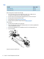
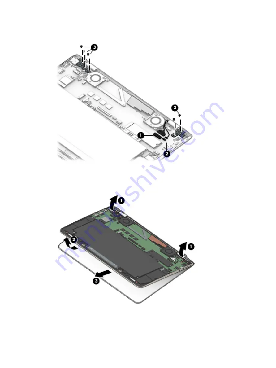
Remove the five Phillips PM2.5×4.1 screws (3) that secure the display assembly to the keyboard/
top cover.
8.
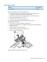
Release the display hinges (1) by swinging them up and back as far as they will go.
9.
Swing the front edge of the keyboard/top cover (2) up and back until it rests at an angle.
10.
Slide the keyboard/top cover (3) forward and separate it from the display assembly.
11.
If it is necessary to replace the display panel assembly or any of the display assembly subcomponents:
a.
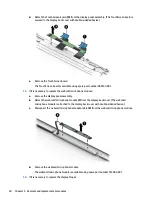
Use a case utility tool (1) or similar plastic, flat-edged tool to separate the top edge of the display
panel assembly (2) from the display back cover.
Component replacement procedures
37
Summary of Contents for CTO 13t-ab000
Page 4: ...iv Safety warning notice ...
Page 7: ...11 Recycling 66 Index 67 vii ...
Page 8: ...viii ...
Page 23: ...Computer major components Computer major components 15 ...

