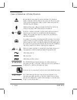
International caution symbol (refer to manual): the product is
marked with this symbol when it is necessary for the user to refer
to the instruction manual in order to protect themselves and the
instrument against damage.
Indicates dangerous voltage (terminals fed from the interior by
voltage exceeding 1000 volts must also be marked).
Protective conductor terminal. For protection against electrical
shock in case of a fault. Used with field wiring terminals to
indicate the terminal that must be connected to ground before
operating equipment.
Low-noise or noiseless, clean ground (earth) terminal. Used for a
signal common, as well as providing protection against electrical
shock in case of a fault. A terminal marked with this symbol must
be connected to ground in the manner described in the installation
(operating) manual, and before operating the equipment.
Frame or chassis terminal. A connection to the frame (chassis) of
the equipment, which normally includes all exposed metal.
Alternating current
Direct current
Alternating or direct current
The WARNING sign denotes a hazard. It calls attention to a
procedure, practice, or the like, which, if not correctly performed
or adhered to, could result in personal injury.
The CAUTION sign denotes a hazard. It calls attention to an
operating procedure, practice, or the like, which, if not correctly
performed or adhered to, could result in damage to or destruction
of part or all of the product.
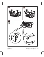
Take care not to cut yourself on the encoder strip inside the plotter.
Summary of Contents for Designjet 230
Page 1: ... ...
Page 3: ... ...
Page 13: ... ...
Page 18: ... ...
Page 19: ... ...
Page 22: ... ...
Page 23: ... ...
Page 25: ... ...
Page 28: ... ...
Page 29: ...3Ć7 Installation and Configuration C4699Ć90000 E A0Ćsize plotters only 32Kg 71 lb ...
Page 31: ... 2 1 ...
Page 32: ... ...
Page 33: ... ...
Page 39: ... ...
Page 43: ... ...
Page 59: ... ...
Page 63: ... ...
Page 64: ... Ensure that the cartridge caps are clean the wipers straight and the openings clear ...
Page 66: ... 2 1 ...
Page 69: ... ...
Page 73: ... Clip ...
Page 76: ... 5 5 mm Torx 15 ...
Page 78: ... Torx 15 Leave loose 5 5 mm Tighten slightly Torx 15 Tighten slightly ...
Page 81: ... Torx 20 ...
Page 93: ... Trailing cable under tabs ...
Page 96: ... ...
Page 103: ... the left and right sideĆplates or the lift mechanism will not work ...
Page 109: ... ...
Page 121: ... GO NO GO ...
Page 135: ... ...
Page 137: ... Flashing Can be On or Off Off On ...
Page 168: ... ...
Page 196: ... ...
Page 197: ... ...
Page 202: ... ...
Page 203: ... ...
Page 207: ... ...
Page 209: ...10Ć7 Parts and Diagrams C4699Ć90000 Top and Back Covers Electronics Trailing Cable ...
Page 211: ... ...
Page 213: ... ...
Page 215: ...10Ć13 Parts and Diagrams C4699Ć90000 CarriageĆAxis Right End ...
Page 217: ... ...
Page 219: ... ...
Page 221: ... ...
Page 223: ... ...
Page 225: ... ...
Page 227: ... ...
Page 233: ... ...
Page 242: ......
Page 243: ... ...
Page 249: ... ...


