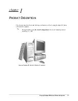
Compaq Deskpro EN Series of Personal Computers
1-3
1.2.1
Desktop Design Overview
The desktop models of the Compaq Deskpro EN Series of Personal Computers use a
highly serviceable chassis to house the slide-out system board, expansion card cage,
power supply, and mass storage devices. The expansion card cage houses the expansion
card.
All internal components are accessible when the cover with its integrated front bezel is
removed. The cover assembly is attached to the chassis with Quick Release Cover
Latches; no tools are required to remove the cover assembly.
The system board is easily removed from the chassis after the cover is removed and the
expansion card cage is raised by lifting a pair of top-mounted green levers. Once the
system unit cover has been removed and the expansion card cage raised, there is no need
to remove any other component to access the system board. Details of the disassembly
procedure are found in Chapter 4, “Removal and Replacement Procedures.”
The tilt
drive cage is located on the right side of the chassis, directly in front of the power
supply. Tilting the cage allows full service access to the rear of the drives without the need
for any tools.
The drive cage accommodates one side-mounted internal hard drive and
provides three bays for external access drives.
The drive cage allows drive installation without the use of rails. Two screws on each side
of the drive are used as guides, and drive release latches are used to secure the drives into
the bays. Extra guide screws (standard and metric thread) are provided on the front of the
chassis, to the left of the drive cage for use when installing additional drives.
The expansion card cage with the riser board mounts at a right angle to the system board.
The riser board is secured to the expansion board cage with three screws. Expansion
boards are installed at a right angle into the riser board. A single screw secures each
expansion board to the expansion board cage.
The power supply is mounted in the right rear corner of the chassis. Embedded clips
located on the bottom of the power supply engage cutouts in the floor of the chassis. The
power supply is held in place by three screws that are installed through the rear panel of
the chassis.


