connections. You must make a four-wire connections for the adjustment
procedures.
Adjustment Procedure
Adjustment is performed on each channel, one at a time. Additionally,
voltage output and current output each use unique calibration constants. If
desired, you may adjust only voltage output or current output.
Preparation
Before performing any adjustments, determine if the adjustments are to be
temporary or permanent (refer to the discussion on page 158).
If Permanent
1. Turn off the mainframe.
2. Remove the terminal module (see page 26).
3. Remove the module from the mainframe (see page 21).
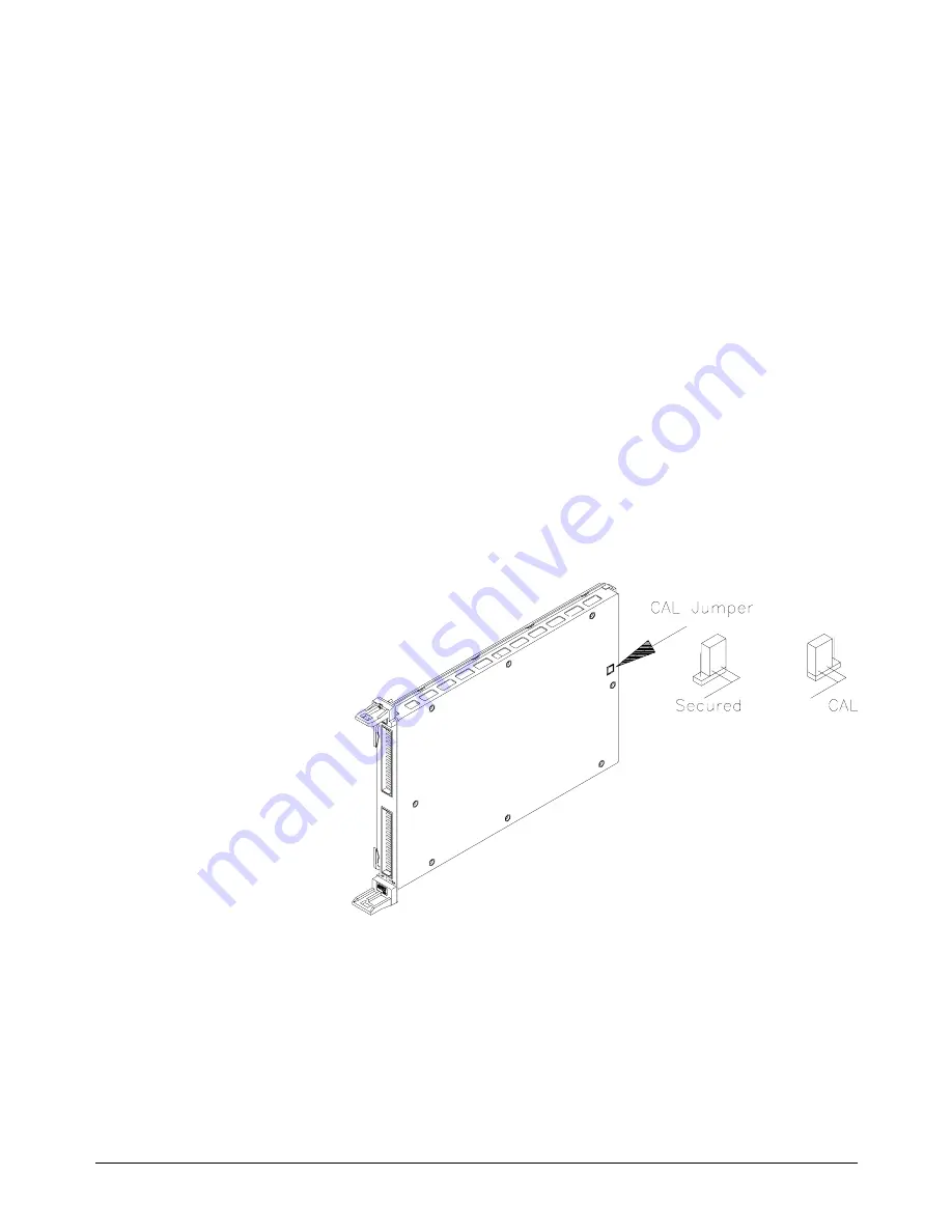
4. Set the Cal Store Enable Jumper to the CAL position as shown in
Figure D-1.
5. Reinstall the module in the mainframe.
6.
Make the CAL output terminal connections on the terminal module.
7. Install the terminal module.
8. Apply power and allow a 15 minute warm-up.
If Temporary
1. Make the CAL output terminal connections on the terminal module.
Figure D-1. CAL Store Enable Jumper
Appendix D
Voltage/Current Output Adjustment 159
Summary of Contents for E1418A
Page 6: ...Notes 6 Contents HP E1418A 8 16 Channel D A Converter Module ...
Page 10: ...Notes 10 HP E1418A User s Manual ...
Page 12: ...12 HP E1418A User s Manual ...
Page 105: ...TRIGger 105 HP E1418A SCPI Command Reference Chapter 3 ...
Page 111: ...Notes HP E1418A Command Quick Reference 111 HP E1418A SCPI Command Reference Chapter 3 ...
Page 135: ...135 HP E1418A Register Based Programming Appendix B ...
Page 157: ...Notes 156 HP E1418A Error Messages Appendix C ...
Page 170: ...Notes Appendix D Voltage Current Output Adjustment 169 ...
Page 174: ...Figure E 1 8 Channel Disassembly 172 Configuration and Disassembly Appendix E ...
Page 175: ...Figure E 2 16 Channel Disassembly Appendix E Configuration and Disassembly 173 ...
Page 192: ...Notes 192 HP E1418A 8 16 Channel D A Converter Module Index ...


