Note
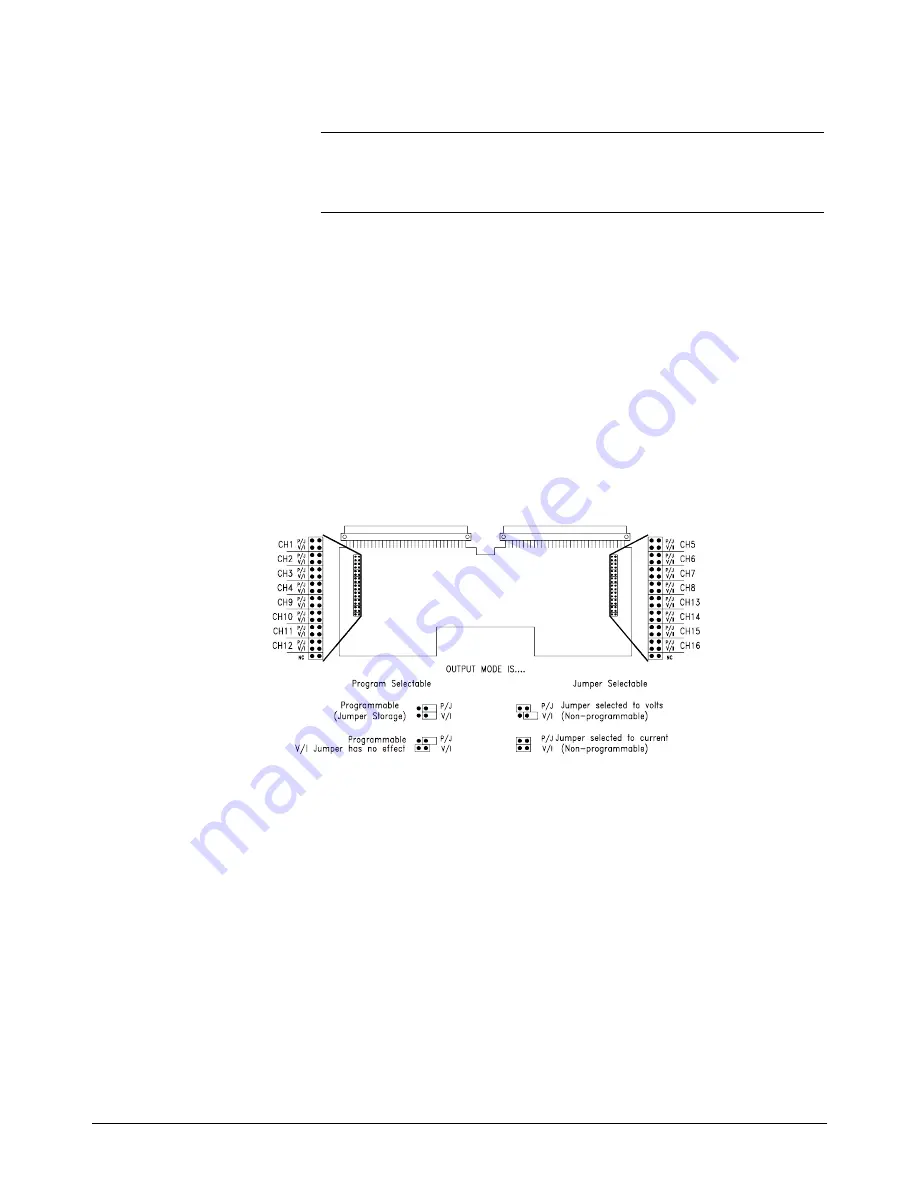
With no jumpers installed, the module will be in the Program Selectable
output mode.
•
If you are using a terminal module dedicated to testing the HP E1418A,
you can remove all the jumpers or put the jumpers in the storage
position.
•
If you are using the end-user’s terminal module, record the positions of
the jumpers. Set the P/J jumpers to the programmable position. Before
returning the module to use, restore the P/J jumpers to their original
position.
Terminal Module
Connections
The Verification Tests require four-wire connections at each channel. The
Adjustment procedures can be performed using a single connections at the
CAL terminals. Additional connection information is given in the
procedures in Chapters 4 and 5 of this manual.
Prepare the
Command Module
All verification and adjustment procedures in this manual use SCPI
(Standard Commands for Programmable Instruments). Prepare the
command module by downloading the SCPI driver named “ E1418".
Downloading instructions are given in the Installing Device Drivers
installation note.
Figure 2-1. P/J and V/I Jumpers
Chapter 2
Installation 17
Summary of Contents for E1418A
Page 4: ...Notes 4 HP E1418A 8 16 Channel D A Converter Service Manual Contents ...
Page 8: ...Notes 8 HP E1418A D A Converter Module Service Manual ...
Page 58: ...Notes 58 Verification Tests Chapter 4 ...
Page 66: ...Figure 5 5 Internal Resistor Adjustment Connections 66 Adjustments Chapter 5 ...
Page 81: ...Figure 6 1 8 Channel Disassembly Chapter 6 Service 81 ...
Page 82: ...Figure 6 2 16 Channel Disassembly 82 Service Chapter 6 ...
Page 84: ...Notes 84 Service Chapter 6 ...
Page 90: ...Figure 7 1 HP E1418A Replaceable Parts 90 Replaceable Parts Chapter 7 ...
Page 91: ...Figure 7 2 Common Terminal Module Replaceable Parts Chapter 7 Replaceable Parts 91 ...


