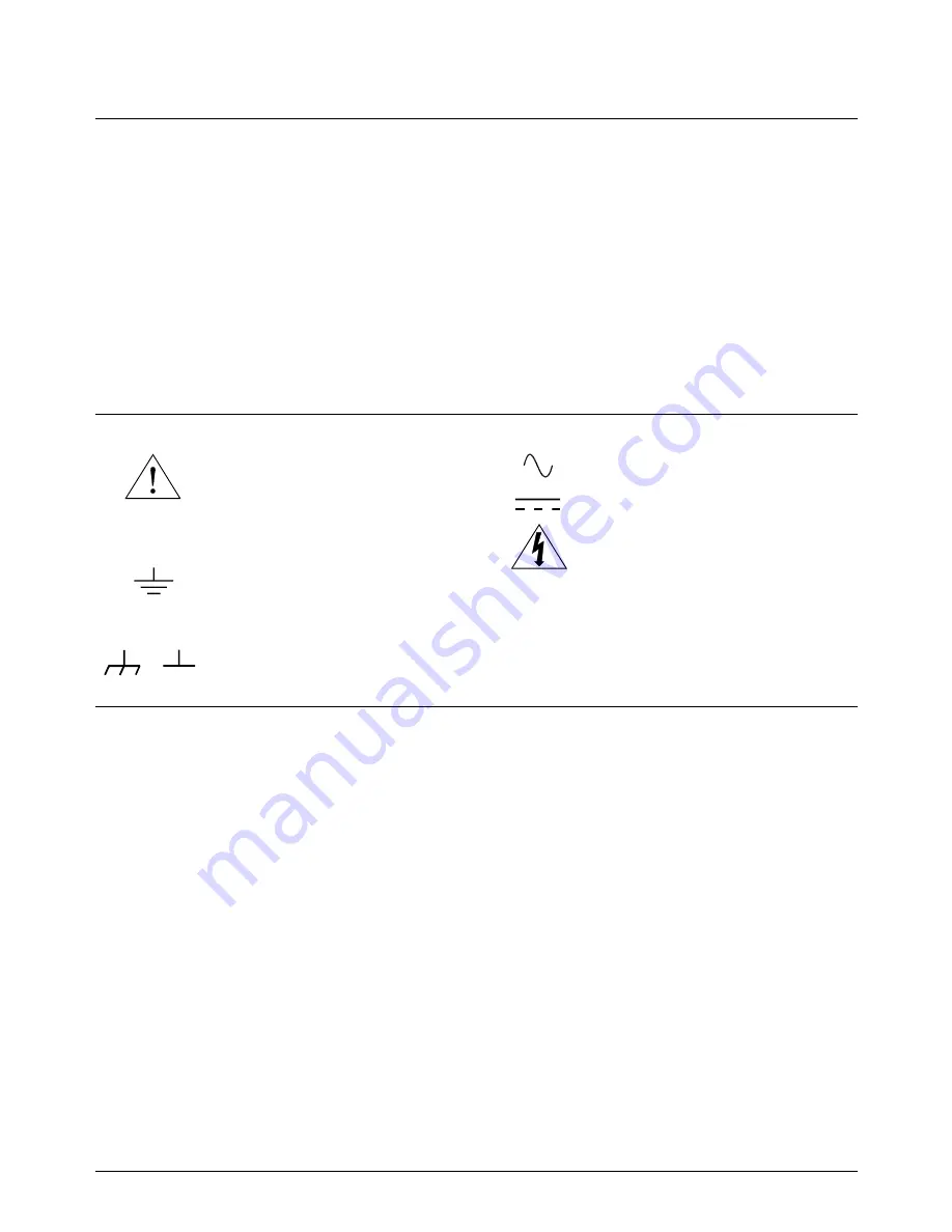
Frame or chassis ground terminal—typi-
cally connects to the equipment’s metal
frame.
Alternating current (AC).
Direct current (DC).
Indicates hazardous voltages.
Calls attention to a procedure, practice, or
condition that could cause bodily injury or
death.
Calls attention to a procedure, practice, or con-
dition that could possibly cause damage to
equipment or permanent loss of data.
Indicates the field wiring terminal that must
be connected to earth ground before operat-
ing the equipment—protects against electri-
cal shock in case of fault.
Instruction manual symbol affixed to prod-
uct. Indicates that the user must refer to the
manual for specific WARNING or CAU-
TION information to avoid personal injury
or damage to the product.
or
WARNINGS
The following general safety precautions must be observed during all phases of operation, service, and repair of this product.
Failure to comply with these precautions or with specific warnings elsewhere in this manual violates safety standards of design,
manufacture, and intended use of the product. Hewlett-Packard Company assumes no liability for the customer’s failure to
comply with these requirements.
Ground the equipment: For Safety Class 1 equipment (equipment having a protective earth terminal), an uninterruptible safety earth
ground must be provided from the mains power source to the product input wiring terminals or supplied power cable.
DO NOT operate the product in an explosive atmosphere or in the presence of flammable gases or fumes.
For continued protection against fire, replace the line fuse(s) only with fuse(s) of the same voltage and current rating and type.
DO NOT use repaired fuses or short-circuited fuse holders.
Keep away from live circuits: Operating personnel must not remove equipment covers or shields. Procedures involving the removal
of covers or shields are for use by service-trained personnel only. Under certain conditions, dangerous voltages may exist even with the
equipment switched off. To avoid dangerous electrical shock, DO NOT perform procedures involving cover or shield removal unless
you are qualified to do so.
DO NOT operate damaged equipment: Whenever it is possible that the safety protection features built into this product have been im-
paired, either through physical damage, excessive moisture, or any other reason, REMOVE POWER and do not use the product until
safe operation can be verified by service-trained personnel. If necessary, return the product to a Hewlett-Packard Sales and Service Of-
fice for service and repair to ensure that safety features are maintained.
DO NOT service or adjust alone: Do not attempt internal service or adjustment unless another person, capable of rendering first aid
and resuscitation, is present.
DO NOT substitute parts or modify equipment: Because of the danger of introducing additional hazards, do not install substitute
parts or perform any unauthorized modification to the product. Return the product to a Hewlett-Packard Sales and Service Office for
service and repair to ensure that safety features are maintained.
WARNING
CAUTION
Documentation History
All Editions and Updates of this manual and their creation date are listed below. The first Edition of the manual is Edition 1. The Edi-
tion number increments by 1 whenever the manual is revised. Updates, which are issued between Editions, contain replacement pages
to correct or add additional information to the current Edition of the manual. Whenever a new Edition is created, it will contain all of
the Update information for the previous Edition. Each new Edition or Update also includes a revised copy of this documentation his-
tory page.
Edition 1 . . . . . . . . . . . . . . . . . . . . . . . . . . . . . . . . . . . . . . . . . . . . . . August 1996
Safety Symbols
6 HP E1418A D/A Converter Module Service Manual
Summary of Contents for E1418A
Page 4: ...Notes 4 HP E1418A 8 16 Channel D A Converter Service Manual Contents ...
Page 8: ...Notes 8 HP E1418A D A Converter Module Service Manual ...
Page 58: ...Notes 58 Verification Tests Chapter 4 ...
Page 66: ...Figure 5 5 Internal Resistor Adjustment Connections 66 Adjustments Chapter 5 ...
Page 81: ...Figure 6 1 8 Channel Disassembly Chapter 6 Service 81 ...
Page 82: ...Figure 6 2 16 Channel Disassembly 82 Service Chapter 6 ...
Page 84: ...Notes 84 Service Chapter 6 ...
Page 90: ...Figure 7 1 HP E1418A Replaceable Parts 90 Replaceable Parts Chapter 7 ...
Page 91: ...Figure 7 2 Common Terminal Module Replaceable Parts Chapter 7 Replaceable Parts 91 ...


