Terminal Module Connections
Each channel has four output lines; HI, LO, HS (Hi Sense), and LS (Low
Sense). When using a channel in the voltage output mode, you can use the
sense lines to increase accuracy or to compensate for long lead lengths. The
sense leads are not used in the current output mode.
Voltage and
Current Output
Connections
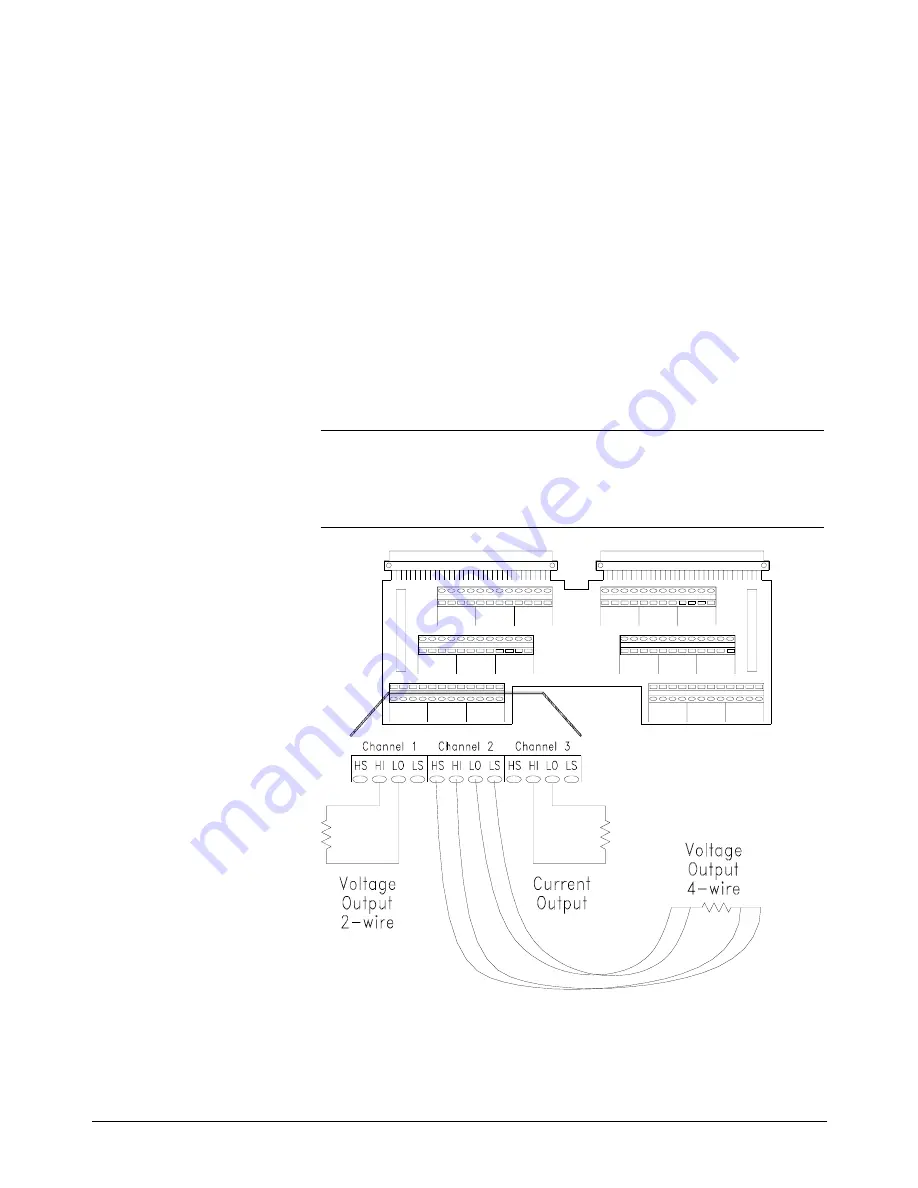
Figure 1-14 shows connections for three types of output. Channel 1 is
connected in the 2-wire voltage output mode, the sense leads are not used
(and the sense connections need not be made). Channel 2 is connected in
the 4-wire voltage output mode. Use this connection for the highest voltage
accuracy and to compensate for long lead lengths. Channel 3 is connected
for current output mode (sense is not used for current output).
Note
The sense leads are internally disconnected for current output. External
wiring may be left connected to the sense outputs on the terminal module
with no effect.
Options A3E and A3H
Terminals
HI, HS, LO, and LS connections are shown on the diagram on page 30.
Figure 1-14. Typical Output Connections
Chapter 1
Module Setup and Installation 33
Summary of Contents for E1418A
Page 6: ...Notes 6 Contents HP E1418A 8 16 Channel D A Converter Module ...
Page 10: ...Notes 10 HP E1418A User s Manual ...
Page 12: ...12 HP E1418A User s Manual ...
Page 105: ...TRIGger 105 HP E1418A SCPI Command Reference Chapter 3 ...
Page 111: ...Notes HP E1418A Command Quick Reference 111 HP E1418A SCPI Command Reference Chapter 3 ...
Page 135: ...135 HP E1418A Register Based Programming Appendix B ...
Page 157: ...Notes 156 HP E1418A Error Messages Appendix C ...
Page 170: ...Notes Appendix D Voltage Current Output Adjustment 169 ...
Page 174: ...Figure E 1 8 Channel Disassembly 172 Configuration and Disassembly Appendix E ...
Page 175: ...Figure E 2 16 Channel Disassembly Appendix E Configuration and Disassembly 173 ...
Page 192: ...Notes 192 HP E1418A 8 16 Channel D A Converter Module Index ...


