10
HP E1586A Rack Mount Terminal Panel
Analog Inputs
Using Two-Wire
Cabling
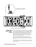
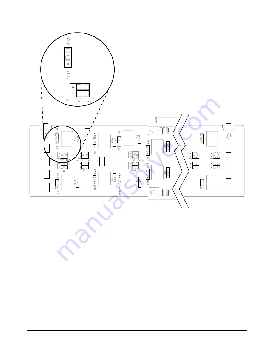
In this configuration, the HI and LO terminals are used for each channel,
without the shield terminal being used. This is not the preferred wiring for
low noise rejection, but may be necessary for certain configurations. For
example, some isolation Signal Conditioning Plug-ons used by the E1413 or
E1415, such as the E1514, E1515, E1516, and E1517, must use this
configuration. This is because those SCPs have no shield connections
available. To configure the Terminal Panel, move the jumpers for each
channel as shown in Figure 6 on page 11.
Since there is no shield available to drive the third winding of the
common-mode transformer, the transformer effectiveness is reduced. To
provide additional high frequency filtering, RC filters are provided on the
board.
Use of the filters decreases the low-frequency Common-mode Rejection to
about 90 dB at 60 Hz, and the measurement bandwidth to about 10 kHz for
the E1413 or E1415.
Figure 5. Option 001 Three-Wire Cable Configuration
RC Filters Removed from Signal Path and
Common-mode Transformer Enabled
Summary of Contents for E1586A
Page 2: ...2 Contents ...


