background image

HP E1586A Rack Mount Terminal Panel  

15

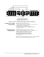
Example Using a Single

Terminal Panel:

SENS:REF THER,5000,1,(@100,101,102) 

measures reference temperature measurements on channels 100 to 102

 SENS:FUNC:TEMP TC,K,.06,(@103:131)

defines channels for temperature measurements 

ROUT:SEQ:DEF (@100,103:107,101,108:123,102,124:131) 

defines the scan list

Example Using Two

Terminal Panels:

SENS:REF THER,5000,1,(@100,101,102,132,133,134) 

measures reference temperature measurements on channels 100 to 102

SENS:FUNC:TEMP TC,K,.06,(@103:131,135:163) 

defines channels for temperature measurements 

ROUT:SEQ:DEF (@100,103:107,101,108:123,102, 
124:131,132,135:139,133,140:155,134,156:163) 

defines the scan list

Note that each reference channel (100, 101, 102, 132, 133, 134) immediately 
precedes its associated measurement channels in the scan list.

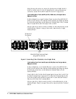
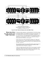
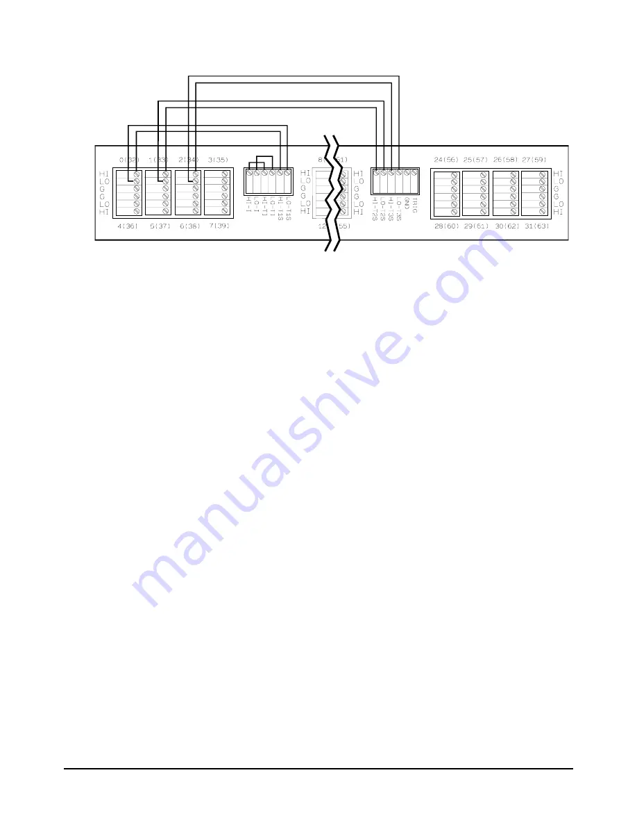
Figure 10. Left, Center, and Right Thermistor Measurements on a Single Panel

One HP E1586 Terminal Panel

Measuring Three Thermistors

on Reference Channels 100, 101, 102

Summary of Contents for E1586A

Page 1: ...e Measurements 7 Mounting the HP E1586 Terminal Panel 7 Reference Thermistor Connections and Operations 7 Using the Option 001 RF Filter 9 Analog Inputs Using Three wire Cabling 9 Analog Inputs Using Two Wire Cabling 10 Configuration for HP E1413 E1415 with Digital I O SCPs 11 Typical Reference Temperature Measurements 12 Measuring Using the Center Thermistor 13 Measuring Using the Left Center and...

Page 2: ...2 Contents ...

Page 3: ...yer supplied products or interfacing unauthorized modification or misuse operation outside of the environmental specifications for the product or improper site preparation or maintenance The design and implementation of any circuit on this product is the sole responsibility of the Buyer HP does not warrant the Buyer s circuitry or malfunctions of HP products that result from the Buyer s circuitry ...

Page 4: ...current rating and type DO NOT use repaired fuses or short circuited fuse holders Keep away from live circuits Operating personnel must not remove equipment covers or shields Procedures involving the removal of covers or shields are for use by service trained personnel only Under certain conditions dangerous voltages may exist even with the equipment switched off To avoid dangerous electrical shoc...

Page 5: ...nel can be ordered with optional High Frequency Common Mode Filters i e HP E1586 Option 001 RF Filters These filters are connected to the input terminal and are used to filter out AC common mode signals present in the cables that connect between the terminal panel and the device under test The filters are useful for filtering out small common mode signals below 5 Vp p To order these filters order ...

Page 6: ...on LO is for Low connections and G is for Guard connections Each terminal set also includes channel numbers like 0 32 4 36 etc where the numbers outside the parenthesis indicate channels 00 31 and the numbers inside the parenthesis indicate channels 32 63 These numbers and the HI LO and G terminals correspond directly to the channel numbers and input terminals of the HP E1413C and E1415A Figure 1 ...

Page 7: ...ns and Operations The HP E1586 Terminal Panel s three thermistors are located next to the channel 3 terminal block between channels 11 and 16 and next to channel 24 see Figure 2 on page 7 Thermistor Excitation Sources Both an HP E1413C or E1415A provides a 122uA current source as the excitation for the thermistors This is available on the Terminal Panel s terminals labeled HI I and LO I For other ...

Page 8: ...shows the connection for a single Terminal Panel Connecting Two Terminal Panels for Reference Temperature Measurements In this configuration two Terminal Panels are used with an HP E1413C E1415A to provide up to 64 channels for temperature measurements Make the following connections on the thermistor terminal blocks of both Terminal Panels Connect HI I to HI TI of the First Terminal panel Connect ...

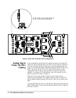
Page 9: ...nfigured for various wiring and Signal Conditioning Plug on SCP combinations for the HP E1413 E1415 Analog Inputs Using Three wire Cabling In this configuration the HI LO and shield terminals are used for each channel This is the preferred wiring for configuration of low level analog channels and provides the best common mode rejection performance To configure the Terminal Panel move the jumpers f...

Page 10: ...cause those SCPs have no shield connections available To configure the Terminal Panel move the jumpers for each channel as shown in Figure 6 on page 11 Since there is no shield available to drive the third winding of the common mode transformer the transformer effectiveness is reduced To provide additional high frequency filtering RC filters are provided on the board Use of the filters decreases t...

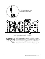
Page 11: ...n low level analog SCPs are used with the digital I O SCP This configuration may make it necessary to connect the digital channels through the E1586 Option 001 board To configure the Terminal Panel when using a digital I O SCP move the jumpers for each affected channel as shown in Figure 7 on page 12 Figure 6 Option 001 Two Wire Cable Configuration RC Filters Placed Into the Signal Path and Common...

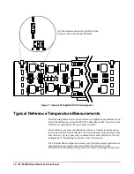
Page 12: ...s on the location of the Terminal Panel For Terminal Panels mounted away from heat sources it is only necessary to measure the center thermistor Use the information in Measuring Using the Center Thermistor For Terminal Panels mounted in such a way that temperature gradients are generated along its length measure all three thermistors Use the information in Measuring Using the Left Center and Right...

Page 13: ...erature measurements These connections are shown in Figure 9 on page 14 Use the information in the HP E1414C E1415A User s manuals to setup the instruments to make the reference measurements The following is an example that uses two Terminal Panels to measure type K thermocouples SENS REF THER 5000 1 100 132 measures reference temperature measurements on channels 100 and 132 SENS FUNC TEMP TC K 06...

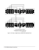
Page 14: ...als to the appropriate thermistor terminals e g channel 100 HI and LO terminals to thermistor 1 HI T1S and LO T1S terminals respectively These connections are shown in Figure 10 on page 15 If two Terminal Panels are used each panel must be connected as above so that both panels provide reference temperature measurements These connections are shown in Figure 11 on page 16 Use the information in the...

Page 15: ...1 100 101 102 132 133 134 measures reference temperature measurements on channels 100 to 102 SENS FUNC TEMP TC K 06 103 131 135 163 defines channels for temperature measurements ROUT SEQ DEF 100 103 107 101 108 123 102 124 131 132 135 139 133 140 155 134 156 163 defines the scan list Note that each reference channel 100 101 102 132 133 134 immediately precedes its associated measurement channels i...

Page 16: ...Rack Mount Terminal Panel Figure 11 Left Center and Right Thermistor Measurements on Multiple Panels Two HP E1586 Terminal Panels Measuring One Thermistor on Each Panel on Reference Channels 100 101 102 132 133 134 ...

Reviews: