HP E1586A Rack Mount Terminal Panel
7
Using the Terminal Panel for Reference Temperature
Measurements
The following explains how to use the Terminal Panel as an isothermal
reference panel for thermocouple measurements. This explanation is for
connections to an HP E1413C High Speed A/D Converter or an HP E1415A
Algorithmic Closed Loop Controller
Mounting the HP
E1586 Terminal
Panel
The Terminal Panel can be mounted in a standard size instrument rack. To
minimize temperature gradients across the panel, it should be mounted in the
rack such that it is away from the other heat sources. The bottom of the rack
is usually the preferred location. Take particular care to minimize the
temperature differences across the horizontal width of the Terminal Panel,
since it is most susceptible to horizontal temperature gradients across its
longest dimension.
Reference
Thermistor
Connections and
Operations
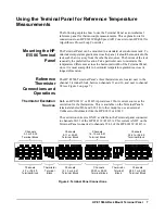
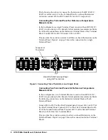
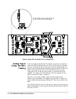
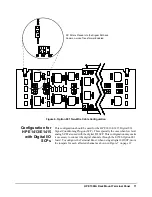
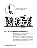
The HP E1586 Terminal Panel’s three thermistors are located next to the
channel 3 terminal block, between channels 11 and 16, and next to channel
24 (see Figure 2 on page 7).
Thermistor Excitation
Sources
Both an HP E1413C or E1415A provides a 122uA current source as the
excitation for the thermistors. This is available on the Terminal Panel’s
terminals labeled HI-I and LO-I. For other modules, use an external
Voltmeter or Multimeter like the HP E1411 or E1412.
The excitation current is ONLY available to the Terminal panel connected
to channels 00-31 of the HP E1413C/E1415A. This current is NOT on the
Terminal Panel connected to channels 32-63 of the HP E1413C/E1415A.
Figure 2. Terminal Panel Connections
Channels
20-23 or 52-55
Terminal Block
Channels
16-19 or 48-51
Terminal Block
Channels
8-11 or 40-43
Terminal Block
Channels
12-15 or 44-47
Terminal Block
Channels
0-3 or 32-35
Terminal Block
Channels
4-7 or 36-39
Terminal Block
Channels
24-27 or 56-59
Terminal Block
Channels
28-31 or 60-63
Terminal Block
Thermistor
Terminal
Block
Thermistor
Terminal
Block
Summary of Contents for E1586A
Page 2: ...2 Contents ...


