HP E1586A Rack Mount Terminal Panel
9
Using the Option 001 RF Filter
The HP E1586 Option 001 Terminal Panel has an additional board that
contains the RF Filters. These filters consist of a 3-winding common-mode
transformers for each channel. These transformers greatly attenuate
common mode signals above 1 kHz. In combination with a properly
connected Option 001 Terminal Panel, the HP E1413C/E1415A can achieve
common mode rejection ratios of >100 dB for signals from DC to >10 Mhz.
These transformers do not limit the measurement bandwidth of the HP
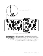
E1413C/E1415A. The RF Filter Board, using on board jumpers, can be
configured for various wiring and Signal Conditioning Plug-on (SCP)
combinations for the HP E1413/E1415.
Analog Inputs
Using Three-wire
Cabling
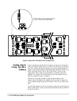
In this configuration, the HI, LO, and shield terminals are used for each
channel. This is the preferred wiring for configuration of low level analog
channels and provides the best common-mode rejection performance. To
configure the Terminal Panel, move the jumpers for each channel as shown
in Figure 5 on page 10.
The configuration in the figure removes the RC-filters from the path and
enables the common-mode transformers. Be sure the side by jumpers are
moved into the same position, or poor Common Mode Rejection will result.
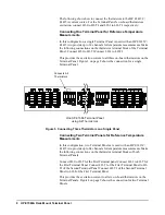
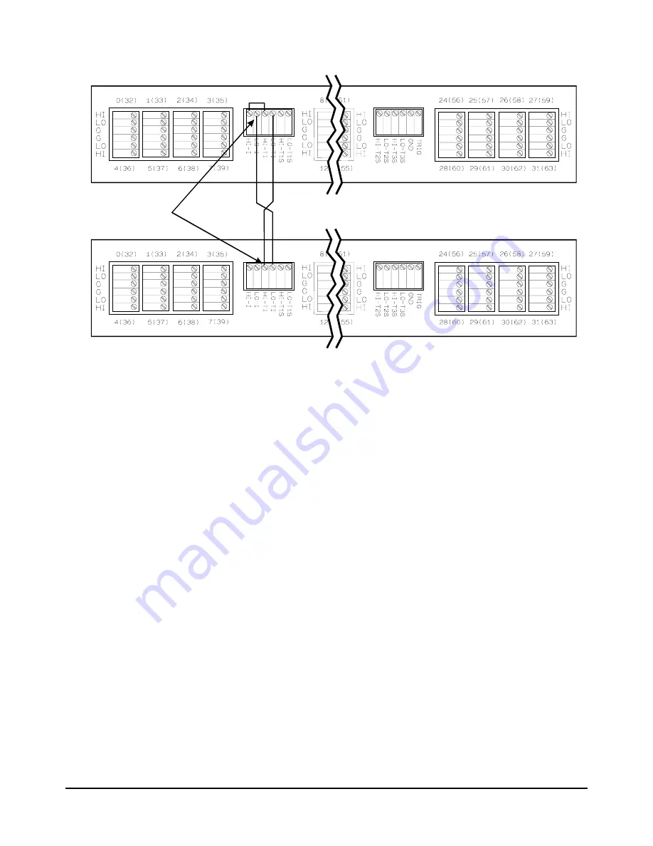
Figure 4. Connecting Six Thermistors on Two Panels
Two HP E1586 Terminal Panels
using All Thermistors on Each Panel
Connect
All Thermistors
on Both Panels
Summary of Contents for E1586A
Page 2: ...2 Contents ...


