background image

Hall sensor board

Description

Spare part number

Hall sensor board (includes cable)

L31343-001

Before removing the hall effects sensor board, follow these steps:

1.

Turn off the computer. If you are unsure whether the computer is off or in Hibernation, turn the 
computer on, and then shut it down through the operating system.

2.

Disconnect the power from the computer by unplugging the power cord from the computer.

3.

Disconnect all external devices from the computer.

4.

Remove the following components:

a.

Display panel (see 

Display panel on page 33

)

b.

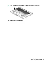
Disconnect the battery cable (see 

Battery on page 36

)

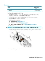
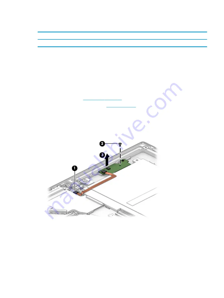
Remove the hall sensor board:

1.

Disconnect the cable from the ZIF connector on the system board (1).

2.

Remove the Phillips M1.6×3.0 screw (2) securing the board.

3.

Remove the board from the computer (3).

Reverse this procedure to replace the hall sensor board.

Component replacement procedures

39

Summary of Contents for Elite x2 1013 G3

Page 1: ...HP Elite x2 1013 G3 Tablet with Collaboration Keyboard Maintenance and Service Guide ...

Page 2: ...erein First Edition June 2018 Document Part Number L32036 001 Product notice This user guide describes features that are common to most models Some features may not be available on your computer Not all features are available in all editions of Windows This computer may require upgraded and or separately purchased hardware drivers and or software to take full advantage of Windows functionality Go ...

Page 3: ... another hard surface such as an adjoining optional printer or a soft surface such as pillows or rugs or clothing to block airflow Also do not allow the AC adapter to contact the skin or a soft surface such as pillows or rugs or clothing during operation The device and the AC adapter comply with the user accessible surface temperature limits defined by the International Standard for Safety of Info...

Page 4: ...iv Safety warning notice ...

Page 5: ... Illustrated parts catalog 18 Computer major components 18 Plastics Kit 21 Miscellaneous parts 22 4 Removal and replacement procedures preliminary requirements 25 Tools required 25 Service considerations 25 Plastic parts 25 Cables and connectors 25 Electrostatic discharge damage 25 Packaging and transporting guidelines 26 Workstation guidelines 27 Equipment guidelines 27 5 Removal and replacement ...

Page 6: ...ton board with audio jack cable 62 Volume board 64 Fingerprint reader board 66 Cable routing 68 7 Backing up restoring and recovering 69 Using Windows tools 69 Creating HP Recovery media select products only 69 Using HP Recovery Manager to create recovery media 70 Before you begin 70 Creating the recovery media 70 Using the HP Cloud Recovery Download Tool to create recovery media 71 Restoring and ...

Page 7: ...e latest HP PC Hardware Diagnostics Windows version 80 Downloading HP Hardware Diagnostics Windows by product name or number select products only 80 Installing HP PC Hardware Diagnostics Windows 80 Using HP PC Hardware Diagnostics UEFI 80 Starting HP PC Hardware Diagnostics UEFI 81 Downloading HP PC Hardware Diagnostics UEFI to a USB flash drive 81 Downloading the latest HP PC Hardware Diagnostics...

Page 8: ...rements for all countries 86 Requirements for specific countries and regions 87 12 Statement of memory volatility 89 Nonvolatile memory usage 91 Questions and answers 93 Using HP Sure Start select models only 94 13 Recycling 95 Index 96 viii ...

Page 9: ...aslim touch screen WUXGA 1920 x 1280 anti glare privacy 3k 2k 3000 2000 BrightView Memory LPDDR3 1866 fine pitch ball grid array FBGA package with 178 balls LPDDR3 2133 fine pitch ball grid array FBGA package with 178 balls Supports dual channel memory Supports up to 16 Gb Supports the following configurations LPDDR3 1866 8 Gb LPDDR3 2133 16 Gb 32 Gb Primary storage Supports M 2 2280 Solid State D...

Page 10: ...2 Combo Adapter non vPro Intel Dual band wireless AC 8265 802 11AC 2x2 WiFi BT 4 2 Combo Adapter VPro WLAN antennas 2 world wide 5 band configured at top of panel on all models Bluetooth Disabled IOPT Support for Wi Fi Specific Absorption Rates SAR in BIOS Compatible with Miracast certified devices Support S3 S4 Wake on wireless LAN Supports WLAN LAN WWAN switching Support HP Connection Optimizer ...

Page 11: ...HP Thunderbolt Dock with 65W adapter supported HP Thunderbolt Dock with 90W adapter supported including Fast Charge HP Elite USB C Docking Station BNB Universal Dock USB C 3 1 Port Replicator Keyboard pointing devices External Collaboration Travel Keyboard Backlit TouchPad requirements Microsoft Precision Touchpad Default Gestures Support Firmware PTP with Filter Driver Hybrid Mode Support Power r...

Page 12: ...Market CPPP Windows 10 Home 64 High End Chinese Market CPPP Windows 10 Home 64 Plus Windows 10 Home 64 Plus Single Language Windows 10 Home 64 Single Language Windows 10 Home 64 StF MSNA for Higher Education Strategic Windows 10 Pro 64 Windows 10 Pro 64 StF MSNA Plus Windows 10 Pro 64 StF MSNA Standard Windows 10 Pro 64 StF MSNA Strategic Serviceability End user replaceable parts AC adapter Slate ...

Page 13: ...ocking station NOTE Cables and or adapters purchased separately may be required 2 USB Type C SuperSpeed port and DisplayPort When the computer is on connects and charges most USB devices that have a Type C connector such as a cell phone camera activity tracker or smartwatch and provides high speed data transfer NOTE Cables and or adapters purchased separately may be required and Connects a Display...

Page 14: ...lp and Support and then select HP Documentation or Select the Start button select HP and then select HP Documentation NOTE When a device is connected to the jack the computer speakers are disabled 2 Volume buttons Control speaker volume on the computer or If the keyboard select products only is not attached press both volume buttons to turn on the SureView application 3 SIM card slot select produc...

Page 15: ... allow a facial recognition logon to Windows instead of a password logon NOTE Camera functions vary depending on the camera hardware and software installed on your product The antennas are not visible from the outside of the computer For optimal transmission keep the areas immediately around the antennas free from obstructions For wireless regulatory notices see the section of the Regulatory Safet...

Page 16: ... button briefly to initiate Sleep When the computer is in the Sleep state press the button briefly to exit Sleep When the computer is in Hibernation press the button briefly to exit Hibernation CAUTION Pressing and holding down the power button results in the loss of unsaved information If the computer has stopped responding and shutdown procedures are ineffective press and hold the power button d...

Page 17: ...tor Connects the computer to the keyboard select products only Rear Component Description 1 Rear camera Allows you to video chat record video and record still images 2 Fingerprint reader select products only Allows a fingerprint logon to Windows instead of a password logon 3 Kickstand Provides stability and a variety of viewing angles Bottom 9 ...

Page 18: ...2 Slide the kickstand away from the tablet and position the kickstand at the desired angle The kickstand will hold at a midway point 1 of about 52 degrees or at full stopping point 2 of about 118 degrees To close the kickstand push the kickstand against the bottom of the tablet until it is flush with the bottom 10 Chapter 2 Components ...

Page 19: ...ard To connect the keyboard lower the computer onto the keyboard until the connectors click into place Removing the keyboard To remove the computer from the keyboard pull the computer away from the back of the keyboard Keyboard area select products only 11 ...

Page 20: ...ds your finger gestures to move the pointer or activate items on the screen 2 Left TouchPad button Functions like the left button on an external mouse 3 Right TouchPad button Functions like the right button on an external mouse 12 Chapter 2 Components ...

Page 21: ...n Microphone is off Off Microphone is on 5 Num lk light On Num lock is on 6 Wireless light On An integrated wireless device such as a wireless local area network WLAN device and or a Bluetooth device is on NOTE On some models the wireless light is amber when all wireless devices are off 7 Sharing or presenting light On Sharing is on 8 Call answer light On Call answer is on 9 Call end light On Call...

Page 22: ...n keys Execute frequently used system functions See Action keys on page 15 5 Embedded numeric keypad A numeric keypad superimposed over the keyboard alphabet keys When num lk is pressed the keypad can be used like an external numeric keypad Each key on the keypad performs the function indicated by the icon in the upper right corner of the key NOTE If the keypad function is active when the computer...

Page 23: ...as long as you hold down the key Turns the keyboard backlight off or on NOTE To conserve battery power turn off this feature Decreases speaker volume incrementally while you hold down the key Increases speaker volume incrementally while you hold down the key Mutes the microphone Mutes or restores speaker sound Turns the wireless feature on or off NOTE A wireless network must be set up before a wir...

Page 24: ...r Office 365 servers Ends a call Declines incoming calls Ends screen sharing NOTE This feature requires Skype for Business or Lync 2013 running on Microsoft Exchange or Office 365 servers NOTE The action key feature is enabled at the factory You can disable this feature by pressing and holding the fn key and the left shift key The fn lock light will turn on After you have disabled the action key f...

Page 25: ... the bottom of a tablet kickstand Service label Provides important information to identify your computer When contacting support you may be asked for the serial number the product number or the model number Locate this information before you contact support Component 1 HP product name 2 Serial number 3 Product ID 4 Warranty period Regulatory label s Provide s regulatory information about the compu...

Page 26: ...rted parts for your computer go to http partsurfer hp com select your country or region and then follow the on screen instructions NOTE Details about your computer including model serial number product key and length of warranty are on the service tag at the bottom of your computer See Labels on page 17 for details 18 Chapter 3 Illustrated parts catalog ...

Page 27: ...ard includes ambient light sensor L31344 001 12 System board includes integrated processor see System board on page 51 Intel Core i7 8650U processor and 16 GB of system memory L31341 601 Intel Core i7 8650U processor and 8 GB of system memory L31978 601 Intel Core i7 8550U processor and 16 GB of system memory L33481 601 Intel Core i7 8550U processor and 8 GB of system memory L31977 601 Intel Core ...

Page 28: ...C L31372 001 256 GB PCIe self encrypting drive SED Opal 2 TLC L31369 001 256 GB PCIe TLC L31370 001 256 GB PCIe L31371 001 128 GB SATA 3 TLC L31367 001 20 Battery 4 cell 50 Wh 937434 855 21 POGO connector and cable L31359 001 22 Back cover For use in models without WWAN L31357 001 For use in models with WWAN L31358 001 23 Kickstand hinges included with back cover L31376 001 24 Kickstand L31377 001...

Page 29: ... 1 Antenna holder insert 2 Fingerprint reader insert 3 SIM tray 4 SIM insert 5 SIM tray insert 6 IR camera bezel 7 HD camera bezel WWAN gasket IR LED tape USB bracket foil speaker gasket thermal long short gasket power button volume button not illustrated Plastics Kit 21 ...

Page 30: ...16131 001 SIM cable L31345 001 Adapters HP USB C to USB 3 0 Adapter 814618 001 HP USB C to VGA Adapter 831751 001 HP USB C to DisplayPort Adapter 831753 001 HP USB C to RJ 45 Adapter 918779 001 HP USB C to HDMI 2 0 Adapter 935325 001 HP USB C Travel Hub 919418 001 HP Nano Lock 918431 001 HP Wacom Tweezer L04642 001 Rubber Kit 928645 001 Screw Kit L31362 001 Collaboration Travel Keyboard For use in...

Page 31: ... For use in Romania L29965 271 For use in Russia L29965 251 For use in Saudi Arabia L29965 171 For use in Slovenia L29965 BA1 For use in South Korea L29965 AD1 For use in Spain L29965 071 For use in Sweden and Finland L29965 B71 For use in Switzerland L29965 BG1 For use in Taiwan L29965 AB1 For use in Thailand L29965 281 For use in Turkey L29965 141 For use in the United Kingdom and Singapore L299...

Page 32: ...a L19349 001 For use in South Africa L19350 001 For use in Taiwan L19353 001 For use in Switzerland L19351 001 For use in Thailand L19352 001 For use in the United Kingdom and Singapore L19354 001 Duck head power cord for use in the United States L27467 001 Duck head power cord for use in Europe and South Korea L31375 001 24 Chapter 3 Illustrated parts catalog ...

Page 33: ...ring the reassembly process Improper cable placement can damage the computer Cables must be handled with extreme care to avoid damage Apply only the tension required to unseat or seat the cables during removal and insertion Handle cables by the connector whenever possible In all cases avoid bending twisting or tearing cables Be sure that cables are routed in such a way that they cannot be caught o...

Page 34: ...6 000 V 800 V 400 V Removing DIPS from plastic tube 2 000 V 700 V 400 V Removing DIPS from vinyl tray 11 500 V 4 000 V 2 000 V Removing DIPS from Styrofoam 14 500 V 5 000 V 3 500 V Removing bubble pack from PCB 26 500 V 20 000 V 7 000 V Packing PCBs in foam lined box 21 000 V 11 000 V 5 000 V Packaging and transporting guidelines Follow these grounding guidelines when packaging and transporting eq...

Page 35: ...traps with a minimum of one megohm 10 resistance in the ground cords To provide proper ground wear a strap snugly against the skin at all times On grounded mats with banana plug connectors use alligator clips to connect a wrist strap When standing use foot straps and a grounded floor mat Foot straps heel toe or boot straps can be used at standing workstations and are compatible with most types of ...

Page 36: ...d by antistatic bags and floor mats Material Use Voltage protection level Antistatic plastics Bags 1 500 V Carbon loaded plastic Floor mats 7 500 V Metallized laminate Floor mats 5 000 V 28 Chapter 4 Removal and replacement procedures preliminary requirements ...

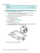
Page 37: ...OTE Details about your computer including model serial number product key and length of warranty are on the service tag on the bottom of your computer See Labels on page 17 for details This chapter provides removal and replacement procedures for Customer Self Repair parts Kickstand Description Kickstand L31377 001 IMPORTANT Make special note of each screw size and location during removal and repla...

Page 38: ...he sides of the kickstand away from the computer 3 and then remove the kickstand 4 Reverse this procedure to replace the kickstand 30 Chapter 5 Removal and replacement procedures for Customer Self Repair parts ...

Page 39: ...uld damage the computer or void the warranty Component replacement procedures NOTE Details about your computer including model serial number product key and length of warranty are on the service tag at the bottom of your computer See Labels on page 17 for details NOTE HP continually improves and changes product parts For complete and current information on supported parts for your computer go to h...

Page 40: ...e system board is removed 1 Position the computer display side up on a flat surface 2 Insert the removal tool or a small straightened paper clip into the card tray access hole until the card tray is ejected 1 3 Remove the tray 2 from the computer and remove the card 3 4 Replace the tray in the computer and then press in gently on the tray 4 until it is firmly seated To install a SIM card reverse t...

Page 41: ...ard IR bezel LCD cable and touch control cable L31886 001 IMPORTANT Make special note of each screw size and location during removal and replacement Before removing the display panel follow these steps 1 Turn off the computer If you are unsure whether the computer is off or in Hibernation turn the computer on and then shut it down through the operating system 2 Disconnect the power from the comput...

Page 42: ...ner of the display panel 1 and then rotate the locking lever down to lock the cup 2 3 Pull the suction tool handle to disengage the panel from the computer 34 Chapter 6 Removal and replacement procedures for Authorized Service Provider parts ...

Page 43: ...attery cable 2 display cable 3 and touch cable 4 from the system board IMPORTANT Be careful when opening to avoid tearing cables Be sure to open from the top Reverse this procedure to replace the display panel Component replacement procedures 35 ...

Page 44: ...isconnect all external devices from the computer 4 Remove the following components Display panel see Display panel on page 33 Remove the battery WARNING To avoid personal injury and damage to the product use extreme care not to puncture twist or crack the battery A puncture or rupture of the battery internally can cause a short with the battery bursting into flames 1 Remove the six Phillips M1 6 3...

Page 45: ...2 Carefully rotate the top of the battery up 1 and the lift the battery out of the computer 2 Reverse this procedure to replace the battery Component replacement procedures 37 ...

Page 46: ... it down through the operating system 2 Disconnect the power from the computer by unplugging the power cord from the computer 3 Disconnect all external devices from the computer 4 Remove the following components a Display panel see Display panel on page 33 b Disconnect the battery cable see Battery on page 36 Remove the solid state drive Using a PH Type 0 Phillips screwdriver remove the Phillips M...

Page 47: ...er from the computer by unplugging the power cord from the computer 3 Disconnect all external devices from the computer 4 Remove the following components a Display panel see Display panel on page 33 b Disconnect the battery cable see Battery on page 36 Remove the hall sensor board 1 Disconnect the cable from the ZIF connector on the system board 1 2 Remove the Phillips M1 6 3 0 screw 2 securing th...

Page 48: ... computer by unplugging the power cord from the computer 3 Disconnect all external devices from the computer 4 Remove the following components a Kickstand see Kickstand on page 29 b Display panel see Display panel on page 33 Remove the kickstand hinges 1 From the bottom rotate the hinges up 1 2 Remove the two Phillips M2 0 3 0 screws from each kickstand hinge 2 and then remove the hinges 3 Pull th...

Page 49: ...tem 2 Disconnect the power from the computer by unplugging the power cord from the computer 3 Disconnect all external devices from the computer 4 Remove the following components a Display panel see Display panel on page 33 b Disconnect the battery see Battery on page 36 Remove the WWAN module 1 Disconnect the antenna cables 1 2 Using a PH Type 0 Phillips screwdriver remove the Phillips M2 0 2 0 sc...

Page 50: ...nals on the module protective sleeves should be installed on the antenna connectors as shown in the following illustration Reverse this procedure to replace the WWAN module 42 Chapter 6 Removal and replacement procedures for Authorized Service Provider parts ...

Page 51: ...the following components a Display panel see Display panel on page 33 b Battery see Battery on page 36 Remove the POGO connector 1 Using a PH Type 0 Phillips screwdriver remove the two Phillips M1 6 1 6 screws 1 IMPORTANT Be sure to use the correct size screwdriver to avoid stripping the screw 2 Disconnect the POGO cable from the ZIF connector on the system board 2 3 Peel the cable up to disengage...

Page 52: ...from the computer 4 Remove the following components a Display panel see Display panel on page 33 b Disconnect the battery cable see Battery on page 36 Remove the camera connector bracket CAUTION Use care to prevent damaging the zero insertion force ZIF connector and ribbon cable 1 Pull back the silver Mylar to access the bracket 1 2 Remove the two Phillips 1 6 2 0 screws 2 and then lift the bracke...

Page 53: ...all external devices from the computer 4 Remove the following components a Display panel see Display panel on page 33 b Disconnect the battery cable see Battery on page 36 c Remove the camera connector bracket see Camera connector bracket on page 44 Remove the camera CAUTION Use care to prevent damaging the zero insertion force ZIF connector and ribbon cable Disconnect the camera cable from the re...

Page 54: ...the computer 4 Remove the following components a Display panel see Display panel on page 33 b Battery see Battery on page 36 c Camera connector bracket see Camera connector bracket on page 44 d IR camera see IR camera on page 45 Remove the front facing HD camera CAUTION Use care to prevent damaging the zero insertion force ZIF connector and ribbon cable Disconnect the camera cable from the reverse...

Page 55: ...all external devices from the computer 4 Remove the following components a Display panel see Display panel on page 33 b Disconnect the battery see Battery on page 36 c Remove the camera connector bracket see Camera connector bracket on page 44 Remove the rear facing camera CAUTION Use care to prevent damaging the zero insertion force ZIF connector and ribbon cable Disconnect the camera cable from ...

Page 56: ...l external devices from the computer 4 Remove the following components a Display panel see Display panel on page 33 b Disconnect the battery cable see Battery on page 36 c IR camera see IR camera on page 45 d HD camera see Front facing HD camera on page 46 e Rear facing camera see Rear facing camera on page 47 Remove the microphone board CAUTION Use care to prevent damaging the zero insertion forc...

Page 57: ...ove speaker cable from the clip on the bezel 1 remove the Phillips M1 6 1 6 screw 2 and then use a tool to remove the bezel from the computer 3 Reverse this procedures to replace the microphone board Component replacement procedures 49 ...

Page 58: ... external devices from the computer 4 Remove the following components a Display panel see Display panel on page 33 b Disconnect the battery cable see Battery on page 36 c Remove the camera connector bracket see Camera connector bracket on page 44 Remove the IR LED module CAUTION Use care to prevent damaging the zero insertion force ZIF connector and ribbon cable Disconnect the camera cable from th...

Page 59: ...31356 001 IMPORTANT Make special note of each screw size and location during removal and replacement Before removing the system board follow these steps 1 Turn off the computer If you are unsure whether the computer is off or in Hibernation turn the computer on and then shut it down through the operating system 2 Disconnect the power from the computer by unplugging the power cord from the computer...

Page 60: ...ew 2 that secures the volume cable and then disconnect the cable from the system board ZIF connector 3 4 Loosen the three Phillips screws in the middle of the heat sink 4 5 Remove the two Phillips M1 6 2 0 screws 5 from the USB bracket 6 Remove the four Phillips M1 6 2 0 screws 6 from the top of the system board 7 Remove the Phillips M1 6 3 0 screw 7 from the right fan 52 Chapter 6 Removal and rep...

Page 61: ... 8 from the left fan 9 Lift the heat sink up to a 90 degree angle 1 10 Lift the left edge of the system board 2 and then pull it away from the connectors to remove it 3 11 If a SIM blank is installed remove it from the system board Component replacement procedures 53 ...

Page 62: ...en removing the system board Reverse this procedure to replace the system board IMPORTANT When installing a new system board the thermal grease and thermal pads must be replaced See Heat sink on page 56 for more information 54 Chapter 6 Removal and replacement procedures for Authorized Service Provider parts ...

Page 63: ... by unplugging the power cord from the computer 3 Disconnect all external devices from the computer 4 Remove the following components a Display panel see Display panel on page 33 b Disconnect the battery cable see Battery on page 36 Remove the antennas 1 Disconnect the WWAN antennas from the WWAN module 1 and the WLAN antennas from the system board 2 2 Lift the copper tape 3 3 Remove the antenna c...

Page 64: ...rnal devices from the computer 4 Remove the following components a Display panel see Display panel on page 33 b Battery see Battery on page 36 Remove the heat sink 1 In the order indicated on the heat sink remove the five Phillips M1 6 2 5 screws 1 that secure the heat sink to the system board 2 Loosen the three captive Phillips screws 2 that secure the heat sink to the system board 3 Use a tool t...

Page 65: ...s removed Replacement thermal material is included with the heat sink and system board spare part kits Thermal pads are used on the heat sink 2 4 and system board 3 Thermal grease is used on the system board component shown by callout 1 in the following image Reverse this procedure to replace the heat sink Component replacement procedures 57 ...

Page 66: ... on page 36 c Solid state drive see Solid state drive on page 38 d WWAN module see WWAN module select products only on page 41 e Camera connector bracket see Camera connector bracket on page 44 f IR camera see IR camera on page 45 g HD camera see Front facing HD camera on page 46 h Microphone board see Microphone board on page 48 i Rear facing camera see Rear facing camera on page 47 j IR LED modu...

Page 67: ...3 Use a tool to release the right speaker from the adhesive that secures it 3 Reverse this procedure to replace the speakers Component replacement procedures 59 ...

Page 68: ...el on page 33 b Battery see Battery on page 36 c Solid state drive see Solid state drive on page 38 d WWAN module see WWAN module select products only on page 41 e Camera connector bracket see Camera connector bracket on page 44 f IR camera see IR camera on page 45 g HD camera see Front facing HD camera on page 46 h Microphone board see Microphone board on page 48 i Rear facing camera see Rear fac...

Page 69: ...2 Remove the fans from the computer 2 Reverse this procedure to replace the fans Component replacement procedures 61 ...

Page 70: ...te drive see Solid state drive on page 38 d WWAN module see WWAN module select products only on page 41 e Camera connector bracket see Camera connector bracket on page 44 f IR camera see IR camera on page 45 g HD camera see Front facing HD camera on page 46 h Microphone board see Microphone board on page 48 i Rear facing camera see Rear facing camera on page 47 j IR LED module see IR LED module on...

Page 71: ...4 Use a tool to push the power button board up and out of the slot 4 Reverse this procedure to replace the power button board with audio jack cable Component replacement procedures 63 ...

Page 72: ...Solid state drive on page 38 d WWAN module see WWAN module select products only on page 41 e Camera connector bracket see Camera connector bracket on page 44 f IR camera see IR camera on page 45 g HD camera see Front facing HD camera on page 46 h Microphone board see Microphone board on page 48 i Rear facing camera see Rear facing camera on page 47 j IR LED module see IR LED module on page 50 k Sy...

Page 73: ...2 Peel the board cable off the computer 2 and then remove the assembly from the computer 3 Reverse this procedure to replace the volume board Component replacement procedures 65 ...

Page 74: ...s a Display panel see Display panel on page 33 b Battery see Battery on page 36 c Solid state drive see Solid state drive on page 38 d WWAN module see WWAN module select products only on page 41 e Camera connector bracket see Camera connector bracket on page 44 f IR camera see IR camera on page 45 g HD camera see Front facing HD camera on page 46 h Microphone board see Microphone board on page 48 ...

Page 75: ...t the fingerprint reader board 3 to release it from the adhesive securing it and then remove the fingerprint reader board Reverse this procedure to replace the fingerprint reader board Component replacement procedures 67 ...

Page 76: ... routing Use the following image to determine proper cable routing in the computer Antenna cables 1 and speaker cables 2 68 Chapter 6 Removal and replacement procedures for Authorized Service Provider parts ...

Page 77: ...back up your personal information Schedule regular backups to avoid information loss You can use Windows tools to back up personal information and create system restore points and recovery media allowing you to restore from backup refresh the computer and reset the computer to its original state NOTE If computer storage is 32 GB or less Microsoft System Restore is disabled by default For more info...

Page 78: ...RW or BD RE rewritable Blu ray discs which are not compatible with HP Recovery Manager software If your computer does not include an integrated optical drive with DVD writer capability you can use an external optical drive purchased separately to create recovery discs as described above If an external optical drive is used you must connect it directly to a USB port on the computer It cannot be con...

Page 79: ...ition select products only or use the HP Recovery media For more information see Recovering using HP Recovery Manager on page 71 If you have not already created recovery media see Creating HP Recovery media select products only on page 69 Using Factory Reset select products only Restores the computer to its original factory state by deleting all information from the hard drive and recreating the p...

Page 80: ... hard drive is still working The HP Recovery partition select products only allows System Recovery only To start HP Recovery Manager from the HP Recovery partition IMPORTANT For a tablet with a detachable keyboard connect the tablet to the keyboard base before beginning these steps select products only 1 Type recovery in the taskbar search box select HP Recovery Manager and then select Windows Rec...

Page 81: ...y press esc and then press f9 for boot options For tablets without keyboards Turn on or restart the tablet quickly hold down the volume up button and then select f9 or Turn on or restart the tablet quickly hold down the volume down button and then select f9 3 Select the optical drive or USB flash drive from which you want to boot and then follow the on screen instructions Removing the HP Recovery ...

Page 82: ...til the Startup menu is displayed and then tap f10 to enter Computer Setup Using a USB keyboard or USB mouse to start Computer Setup BIOS You can start Computer Setup by using a keyboard or mouse connected to a USB port but you must first disable FastBoot 1 Enter the Boot Device Options menu Computers or tablets with keyboards Turn on or restart the computer and when the HP logo appears press f9 t...

Page 83: ...nus Select the Save icon in the lower right corner of the screen and then follow the on screen instructions or Select Main select Save Changes and Exit and then press enter Your changes go into effect when the computer restarts Restoring factory settings in Computer Setup NOTE Restoring defaults will not change the hard drive mode To return all settings in Computer Setup to the values that were se...

Page 84: ...n the computer is connected to reliable external power using the AC adapter Do not download or install a BIOS update while the computer is running on battery power docked in an optional docking device or connected to an optional power source During the download and installation follow these instructions Do not disconnect power on the computer by unplugging the power cord from the AC outlet Do not ...

Page 85: ... and when the HP logo appears press f9 to enter the Boot Device Options menu Computers or tablets without keyboards Turn off the computer Press the power button in combination with the volume down button until the Startup menu is displayed and then press f9 to enter the Boot Device Options menu 2 Select a boot device press enter and then follow the on screen instructions TPM BIOS settings select p...

Page 86: ...ores the BIOS to its previously safe state without user intervention HP Sure Start is configured and already enabled so that most users can use the HP Sure Start default configuration The default configuration can be customized by advanced users To access the latest documentation on HP Sure Start go to http www hp com support Select Find your product and then follow the on screen instructions 78 C...

Page 87: ...tics Windows select More and then select Run as administrator or To access HP PC Hardware Diagnostics Windows from HP Support Assistant a Type support in the taskbar search box and then select the HP Support Assistant app or Select the question mark icon in the taskbar b Select Troubleshooting and fixes c Select Diagnostics and then select HP PC Hardware Diagnostics Windows 2 When the tool opens s...

Page 88: ...ate to the folder on your computer or the flash drive where the exe file was downloaded double click the exe file and then follow the on screen instructions Using HP PC Hardware Diagnostics UEFI NOTE For Windows 10 S computers you must use a Windows computer and a USB flash drive to download and create the HP UEFI support environment because only exe files are provided For more information see Dow...

Page 89: ...UEFI download instructions are provided in English only and you must use a Windows computer to download and create the HP UEFI support environment because only exe files are provided Downloading the latest HP PC Hardware Diagnostics UEFI version To download the latest HP PC Hardware Diagnostics UEFI version to a USB flash drive 1 Go to http www hp com go techcenter pcdiags The HP PC Diagnostics ho...

Page 90: ...ps 1 Go to http www hp com support 2 Select Get software and drivers select your type of product enter the product name or number in the search box that is displayed select your computer and then select your operating system 3 In the Diagnostics section follow the on screen instructions to select and download the Remote UEFI version for the product Customizing Remote HP PC Hardware Diagnostics UEF...

Page 91: ...omization selections 4 Select Main and then Save Changes and Exit to save your settings Your changes take effect when the computer restarts Using Remote HP PC Hardware Diagnostics UEFI settings select products only 83 ...

Page 92: ...mperature Operating 32 to 95 F 0 to 35 C not writing optical 41 to 95 F 5 to 35 C writing optical Nonoperating 4 to 140 F 20 to 60 C Relative humidity noncondensing Operating 10 to 90 Nonoperating 5 to 95 Shock Operating 40 G 2 ms half sine Nonoperating 240 G 2 ms half sine Random Vibration Operating 1 043 grms Nonoperating 3 50 grms Maximum altitude unpressurized Operating 50 to 10 000 ft 15 24 t...

Page 93: ... 13 0 33 02 cm Brightness 72 CG 450 nits Pixel resolution 3000 2000 3k 2k 1920 x 1280 WUXGA Surface treatment 3k 2k BrightView WUXGA anti glare Interface eDP 1 4 PSR Backlight WLED Viewing angle UWVA 85 85 85 85 Left Right Down Up Display specifications 85 ...

Page 94: ...rements are applicable to all countries and regions The length of the power cord set must be at least 1 0 m 3 3 ft and no more than 2 0 m 6 5 ft All power cord sets must be approved by an acceptable accredited agency responsible for evaluation in the country or region where the power cord set will be used The power cord sets must have a minimum current capacity of 10 A and a nominal voltage rating...

Page 95: ... KTL 5 Sweden SEMKO 1 Switzerland SEV 1 Taiwan BSMI 6 Thailand TISI 1 The United Kingdom ASTA 1 The United States UL 2 1 The flexible cord must be Type HO5VV F 3 conductor 0 75 mm conductor size Power cord set fittings appliance coupler and wall plug must bear the certification mark of the agency responsible for evaluation in the country or region where it will be used 2 The flexible cord must be ...

Page 96: ...r the CCC certification mark 5 The flexible cord must be Type H05VV F 3 conductor 0 75 mm conductor size KTL logo and individual approval number must be on each element Corset approval number and logo must be printed on a flag label 6 The flexible cord must be Type HVCTF 3 conductor 1 25 mm conductor size Power cord set fittings appliance coupler cable and wall plug must bear the BSMI certificatio...

Page 97: ... keyboard base before beginning steps in this chapter Current BIOS steps 1 Follow steps a through l below to restore the nonvolatile memory that can contain personal data Restoring or reprogramming nonvolatile memory that does not store personal data is neither necessary nor recommended a Turn on or restart the computer and then press esc while the Press the ESC key for Startup Menu message is dis...

Page 98: ...or fingerprint reader one or two prompts will appear one to clear the TPM and the other to Reset Fingerprint Sensor press or tap F1 to accept or F2 to reject l Remove all power and system batteries for at least 24 hours 2 Complete one of the following Remove and retain the storage drive or Clear the drive contents by using a third party utility designed to erase data from an SSD or Clear the conte...

Page 99: ... EEPROM 64 KBytes not customer accessible No Yes Stores NIC configuration and NIC firmware NIC EEPROM is programmed using a utility from the NIC vendor that can be run from DOS A utility is required to write data to this memory and is available from the NIC vendor Writing data to this ROM in an inappropriate manner will render the NIC non functional DIMM Serial Presence Detect SPD configuration da...

Page 100: ...sing this utility Bluetooth flash select products only 2 Mbit No Yes Stores Bluetooth configuration and firmware Bluetooth flash is programmed at the factory Tools for writing data to this memory are not publicly available but can be obtained from the silicon vendor A utility is required for writing data to this memory and is made available through newer versions of the driver whenever the flash r...

Page 101: ...ic system diagnostics The UEFI BIOS provides functionality beyond that of the legacy BIOS In addition the UEFI BIOS works to initialize the computer s hardware before loading and executing the OS the run time environment allows the loading and execution of software programs from storage devices to provide more functionality such as advanced hardware diagnostics with the ability to display more det...

Page 102: ...ot Keys a Turn on or restart the computer and then press esc while the Press the ESC key for Startup Menu message is displayed at the bottom of the screen b Select the Security menu select Secure Boot Configuration and then follow the on screen instructions c At the Secure Boot Configuration window select Secure Boot select Clear Secure Boot Keys and then follow the on screen instructions to conti...

Page 103: ...he battery in general household waste Follow the local laws and regulations in your area for battery disposal HP encourages customers to recycle used electronic hardware HP original print cartridges and rechargeable batteries For more information about recycling programs see the HP Web site at http www hp com recycle 95 ...

Page 104: ...ottom 9 display 7 keyboard area 11 kickstand 10 left side 6 rear 9 right side 5 top 8 computer major components 18 Computer Setup navigating and selecting 75 restoring factory settings 75 computer specifications 84 connector power 5 D digital pen product description 2 display specifications 85 display components 7 display panel 33 product description 1 spare part numbers 19 DisplayPort identifying...

Page 105: ...icrophone mute 13 num lock 13 power 8 sharing or presenting 13 wireless 13 M memory nonvolatile 89 volatile 89 memory module product description 1 microphone board spare part numbers 19 48 microphone mute key identifying 15 microphone mute light identifying 13 minimized image recovery 72 minimized image creating 71 model name 1 mute volume action key 15 N nonvolatile memory 89 num lock light 13 O ...

Page 106: ... service labels locating 17 serviceability product description 4 setup utility navigating and selecting 75 restoring factory settings 75 sharing or presenting light identifying 13 SIM card removing 32 SIM insert illustrated 21 SIM slot identifying 6 SIM tray illustrated 21 SIM tray insert illustrated 21 slots security cable 6 SIM card 6 Solid state drive 38 solid state drive spare part number 20 s...

Page 107: ... wireless certification label 17 wireless light identifying 13 wireless product description 2 WLAN antennas identifying 7 WLAN device 17 WLAN label 17 workstation guidelines 27 WWAN spare part number 19 WWAN antennas identifying 7 WWAN module 41 spare part numbers 19 41 Index 99 ...

Reviews: