background image

4.

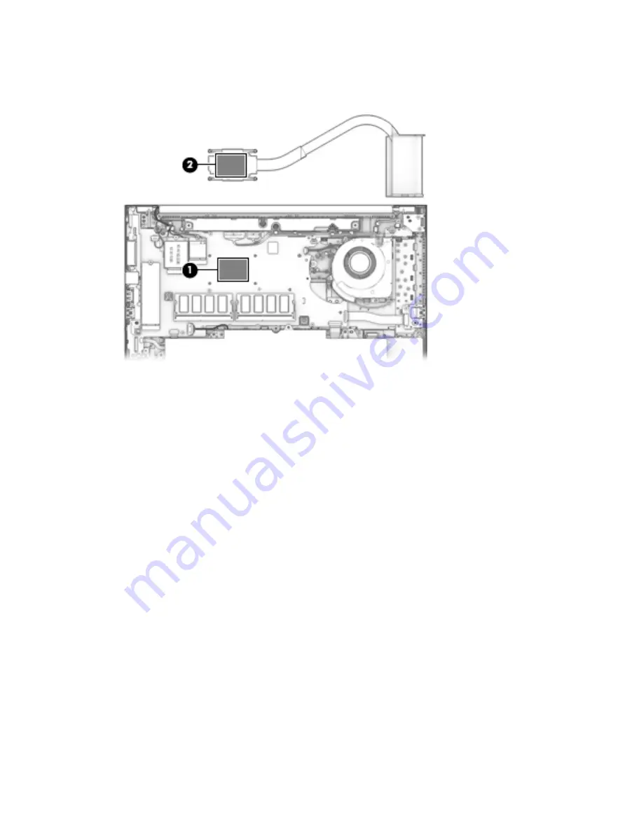
Thoroughly clean the thermal material from the surfaces of the system board component (1) and the 
heat sink (2) each time the heat sink is removed. Replacement thermal material is included with the heat 
sink and system board spare part kits.

Reverse this procedure to install the heat sink.

54

Chapter 6   Removal and replacement procedures for Authorized Service Provider parts

Summary of Contents for EliteBook 850 G5 Notebook PC

Page 1: ...HP EliteBook 850 G5 Notebook PC Maintenance and Service Guide ...

Page 2: ... February 2018 Document Part Number L12982 001 Product notice This user guide describes features that are common to most models Some features may not be available on your computer Not all features are available in all editions of Windows This computer may require upgraded and or separately purchased hardware drivers and or software to take full advantage of Windows functionality Go to http www mic...

Page 3: ...hat should only be accessed by an authorized service provider See Chapter 5 Removal and replacement procedures for Customer Self Repair parts for details Accessing parts described in Chapter 6 Removal and replacement procedures for Authorized Service Provider only parts can damage the computer or void your warranty iii ...

Page 4: ...iv Important Notice about Customer Self Repair Parts ...

Page 5: ...w another hard surface such as an adjoining optional printer or a soft surface such as pillows or rugs or clothing to block airflow Also do not allow the AC adapter to contact the skin or a soft surface such as pillows or rugs or clothing during operation The device and the AC adapter comply with the user accessible surface temperature limits defined by the International Standard for Safety of Inf...

Page 6: ...vi Safety warning notice ...

Page 7: ... 3 Illustrated parts catalog 24 Computer major components 24 Display assembly subcomponents 27 Cable Kit 29 Plastics Kit 30 Miscellaneous parts 31 4 Removal and replacement procedures preliminary requirements 32 Tools required 32 Service considerations 32 Plastic parts 32 Cables and connectors 33 Drive handling 33 Grounding guidelines 34 Electrostatic discharge damage 34 Packaging and transporting...

Page 8: ...eaker assembly 59 Fingerprint reader assembly 60 TouchPad 61 Pointing stick module 63 NFC module 64 Smart card reader 65 Fan 66 System board 68 Display assembly 72 Top cover 82 7 Interpreting system validation diagnostic front panel LEDs and audible codes 83 8 Computer Setup BIOS TPM and HP Sure Start 85 Using Computer Setup 85 Starting Computer Setup 85 Using a USB keyboard or USB mouse to start ...

Page 9: ...to know before you get started 93 Using the HP Recovery partition select products only 94 Using HP Recovery media to recover 95 Changing the computer boot order 95 Removing the HP Recovery partition select products only 95 11 Specifications 96 Computer specifications 96 39 6 cm 15 6 in display specifications 97 M 2 PCIe solid state drive specifications 98 M 2 SATA solid state drive specifications ...

Page 10: ...x ...

Page 11: ...120W or 230W G2 maximum resolution 4K 60Hz DisplayPort 1 and 4K 60Hz DisplayPort 2 with Thunderbolt Internal graphics Intel HD Graphics 620 External graphics AMD Radeon RX 540 2 GB of GPU memory Panel Supports privacy filter and narrow bezel 39 6 cm 15 6 in UWVA non touch Full high definition FHD 1920 1080 anti glare AG 220 nits 45 CG eDP slim without camera FHD 1920 1080 anti glare AG 220 nits 45...

Page 12: ...o 32 GB of system RAM in the following configurations 32768 MB 16384 MB 2 24576 MB 16384 MB 1 8192 MB 1 20480 MB 16384 MB 1 4096 MB 1 16384 MB 16384 MB 1 or 8192 MB 2 12288 MB 8192 MB 1 4096 MB 1 8192 MB 8192 MB 1 or 4096 MB 2 4096 MB 4096 MB 1 Primary storage M 2 solid state drives 2280 1 TB PCIe Gen3 4 SS NVMe TLC 512 GB PCIe Gen3 4 SS NVMe TLC Opal 2 512 GB PCIe Gen3 4 SS NVMe TLC 512 GB SATA 3...

Page 13: ...AC 8265 802 11ac 2 2 WiFi Bluetooth 4 2 Combo Adaptor vPro Intel Dual band wireless AC 8265 802 11ac 2 2 WiFi Bluetooth 4 2 Combo Adaptor non vPro Realtek RTL8822BE 802 11ac 2 2 Wi Fi Bluetooth 4 2 Combo Adapter Two WLAN antennas built into bottom of display assembly Support for models without WLAN Compatible with Miracast certified devices Bluetooth Disabled IOPT Support S3 S4 wake on Wireless LA...

Page 14: ... HP Docking Station Keyboard pointing devices Keyboard HP Collaboration Keyboard with numeric pad Dual point non backlit spill resistant with drain Dual point backlit spill resistant with drain with HP Dura Keys TouchPad Support for Microsoft Precison Touchpad Default Gestures Firmware PTP Point to Point with Filter Driver Support for No Hybrid Mode Power requirements Battery HP Long Life Lithium ...

Page 15: ...card Hardware enforced Firmware Protection HP Hardware Root of Trust Sure Start Gen4 Operating system Preinstalled Windows 10 Home 64 Windows 10 Home 64 Single Language Windows 10 Home 64 Chinese Market CPPP Windows 10 Home 64 High End Chinese Market CPPP Windows 10 Home 64 Plus Windows 10 Home 64 Plus Single Language Win 10 Home Indonesia Market PPP Plus Single Language only for 840 G5 models Win...

Page 16: ...10 Pro 64 OSUSB NeoKylin Linux SRDVD Certified Microsoft WHQL Web only support Windows 10 Enterprise 64 Windows 10 Pro 64 CBB 1703 Windows 10 Enterprise 64 LTSB 1607 Serviceability End user replaceable parts AC adapter Solid state drive Memory module WLAN module WWAN module Keyboard 6 Chapter 1 Product description ...

Page 17: ...t microphone This jack does not support optional standalone microphones WARNING To reduce the risk of personal injury adjust the volume before putting on headphones earbuds or a headset For additional safety information refer to the Regulatory Safety and Environmental Notices To access this guide Select the Start button select HP Help and Support and then select HP Documentation or Select the Star...

Page 18: ... smartwatch and provides high speed data transfer and Connects a display device that has a USB Type C connector providing DisplayPort output NOTE Your computer may also support a Thunderbolt docking station NOTE Cables and or adapters purchased separately may be required 8 Power connector Connects an AC adapter 9 Battery light When AC power is connected White The battery charge is greater than 90 ...

Page 19: ... components NOTE The computer fan starts up automatically to cool internal components and prevent overheating It is normal for the internal fan to cycle on and off during routine operation 3 USB 3 x SuperSpeed port with HP Sleep and Charge Connects a USB device provides high speed data transfer and even when the computer is off charges most products such as a cell phone camera activity tracker or ...

Page 20: ...Display NOTE Refer to the illustration that most closely matches your computer 10 Chapter 2 Components ...

Page 21: ...re cameras are in use 5 WLAN antennas select products only Send and receive wireless signals to communicate with wireless local area networks WLANs The antennas are not visible from the outside of the computer For optimal transmission keep the areas immediately around the antennas free from obstructions For wireless regulatory notices see the section of the Regulatory Safety and Environmental Noti...

Page 22: ...antenna select products only Allows you to wirelessly share information when you tap it with an NFC enabled device The antenna is not visible from the outside of the computer For optimal transmission keep the area immediately around the antenna free from obstructions For wireless regulatory notices see the section of the Regulatory Safety and Environmental Notices that applies to your country or r...

Page 23: ...ock light On Caps lock is on which switches the key input to all capital letters 3 Mute light On Computer sound is off Off Computer sound is on 4 Microphone mute light On Microphone is off Off Microphone is on 5 Wireless light On An integrated wireless device such as a wireless local area network WLAN device and or a Bluetooth device is on NOTE On some models the wireless light is amber when all w...

Page 24: ... Description 8 Call end light On Call end is on 9 Num lk light On Num lock is on 10 Fn lock light On The fn key is locked For more information see Hot keys select products only on page 18 14 Chapter 2 Components ...

Page 25: ... least 5 seconds to turn off the computer To learn more about your power settings see your power options Right click the Power meter icon and then select Power Options 2 Vents 2 Enable airflow to cool internal components NOTE The computer fan starts up automatically to cool internal components and prevent overheating It is normal for the internal fan to cycle on and off during routine operation 3 ...

Page 26: ...e the Start menu 4 Action keys Execute frequently used system functions See Action keys on page 17 5 num lk key Turns the embedded numeric keypad on and off or Alternates between the navigational and numeric functions on the integrated numeric keypad 6 Integrated numeric keypad A separate keypad to the right of the alphabet keyboard When num lk is pressed the integrated keypad can be used like an ...

Page 27: ...y setting press fn p Decreases the screen brightness incrementally as long as you hold down the key Increases the screen brightness incrementally as long as you hold down the key Mutes or restores speaker sound Decreases speaker volume incrementally while you hold down the key Increases speaker volume incrementally while you hold down the key Mutes the microphone Turns the keyboard backlight off o...

Page 28: ...e is enabled at the factory You can disable this feature by pressing and holding the fn key and the left shift key The fn lock light will turn on After you have disabled the action key feature you can still perform each function by pressing the fn key in combination with the appropriate action key Hot keys select products only A hot key is the combination of the fn key and another key To use a hot...

Page 29: ...nt Enables airflow to cool internal components NOTE The computer fan starts up automatically to cool internal components and prevent overheating It is normal for the internal fan to cycle on and off during routine operation Bottom 19 ...

Page 30: ...nation Hibernation is a power saving state that uses the least amount of power 2 Wireless light On An integrated wireless device such as a wireless local area network WLAN device and or a Bluetooth device is on NOTE On some models the wireless light is amber when all wireless devices are off 3 Drive light Blinking white The hard drive is being accessed Amber HP 3D DriveGuard has temporarily parked...

Page 31: ...Cover Component Description Internal microphone s Record s sound Cover 21 ...

Page 32: ...e bottom of a tablet kickstand Service label Provides important information to identify your computer When contacting support you may be asked for the serial number the product number or the model number Locate this information before you contact support Your service label will resemble one of the examples shown below Refer to the illustration that most closely matches the service label on your co...

Page 33: ...label s Provide s regulatory information about the computer Wireless certification label s Provide s information about optional wireless devices and the approval markings for the countries or regions in which the devices have been approved for use Labels 23 ...

Page 34: ...rted parts for your computer go to http partsurfer hp com select your country or region and then follow the on screen instructions NOTE Details about your computer including model serial number product key and length of warranty are on the service tag at the bottom of your computer See Labels on page 22 for details 24 Chapter 3 Illustrated parts catalog ...

Page 35: ... 9 Power button board L14374 001 10 USB board includes bracket L14380 001 11 Fingerprint reader assembly includes cable L13681 001 12 Speakers includes cable L14368 001 13 NFC module includes antenna and TouchPad foam L14385 001 14 Smart card reader board includes cable L18312 001 15 System board includes processor and replacement thermal material see System board on page 68 All system boards use ...

Page 36: ...851592 001 Intel Dual band wireless AC 8265 802 11AC 2x2 WiFi Bluetooth 4 2 Combo Adaptor non vPro 851594 001 21 WWAN module LTE CAT4 Huawei HP lt4132 LTE HSPA w GPS M 2 845710 003 LTE CAT9 Fibocom Intel XMM 7360 LTE Advanced 917823 001 22 Solid state drive SSD 1 TB PCIe Gen3 4 NVMe TLC L17246 001 512 GB PCIe Gen3 4 SS NVMe TLC L17251 001 512 GB PCIe Gen3 4 Self encrypting drive SED Opal 2 TLC L17...

Page 37: ...era shutter L15527 001 For use in models with an IR camera includes camera shutter L15528 001 For use in models with an IR camera and an ambient light sensor includes camera shutter L15529 001 2 Raw display panel includes panel touch module as applicable display cable and interior panel bezel FHD 220 nits L16640 001 FHD 400 nits L16641 001 Display assembly subcomponents 27 ...

Page 38: ...01 Microphone module not shown includes double sided tape L15512 001 6 Camera cable HD and IR models L14361 001 Cable Kit 7 Hinges left and right for use in models with touch displays L14364 001 Hinge Kit Hinges left and right for use in models with non touch displays L14365 001 Hinge Kit 8 WLAN antenna spared with display enclosure 9 WWAN antenna spared with display enclosure 10 Display cable L14...

Page 39: ...Cable Kit Item Description Spare part number Cable Kit includes L14361 001 1 Keyboard cable 2 USB board cable 3 Card reader cable 4 TouchPad cable 5 Fingerprint reader cable 6 NFC cable Cable Kit 29 ...

Page 40: ...Plastics Kit Item Component Spare part number Plastics kit L17376 001 1 SIM card reader insert 2 Fingerprint reader insert 3 Smart card reader insert 30 Chapter 3 Illustrated parts catalog ...

Page 41: ...850 45 W HP Smart AC adapter 2 prong 742436 001 45 W HP Smart AC Adapter 741553 850 45 W HP Smart AC Adapter for use in Argentina 741553 852 45 W wall mount 3 pin USB C 860210 850 Power cord 3 pin black C5 1 0 m Europe Austria Belgium Finland France Germany the Netherlands Norway and Sweden 923430 004 Screw Kit L18441 001 Pointing stick covers quantity of 20 L15396 001 Miscellaneous parts 31 ...

Page 42: ...f the considerations that you must keep in mind during disassembly and assembly procedures NOTE As you remove each subassembly from the computer place the subassembly and all accompanying screws away from the work area to prevent damage Plastic parts CAUTION Using excessive force during disassembly and reassembly can damage plastic parts Use care when handling the plastic 32 Chapter 4 Removal and ...

Page 43: ...nserting a hard drive shut down the computer If you are unsure whether the computer is off or in Hibernation turn the computer on and then shut it down through the operating system Before handling a drive be sure that you are discharged of static electricity While handling a drive avoid touching the connector Before removing a diskette drive or optical drive be sure that a diskette or disc is not ...

Page 44: ... components in their electrostatic safe containers until you are ready to install them Before touching an electronic component discharge static electricity by using the guidelines described in this section Avoid touching pins leads and circuitry Handle electronic components as little as possible If you remove a component place it in an electrostatic safe container The following table shows how hum...

Page 45: ... to ground and that proper materials are selected to avoid static charging When grounding is not possible use an ionizer to dissipate electric charges Workstation guidelines Follow these grounding workstation guidelines Cover the workstation with approved static shielding material Use a wrist strap connected to a properly grounded work surface and use properly grounded tools and equipment Use cond...

Page 46: ...operator and ground To be effective the conductive must be worn in contact with the skin The following grounding equipment is recommended to prevent electrostatic damage Antistatic tape Antistatic smocks aprons and sleeve protectors Conductive bins and other assembly or soldering aids Nonconductive foam Conductive tabletop workstations with ground cords of one megohm resistance Static dissipative ...

Page 47: ...rent information on supported parts for your computer go to http partsurfer hp com select your country or region and then follow the on screen instructions There are as many as 16 screws that must be removed replaced and or loosened when servicing Customer Self Repair parts Make special note of each screw size and location during removal and replacement Bottom cover Description Spare part number B...

Page 48: ...ews 2 that secure the bottom cover 3 Starting under the middle of the display pry 1 and lift the bottom cover off the computer 2 Reverse the removal procedures to install the bottom cover 38 Chapter 5 Removal and replacement procedures for Customer Self Repair parts ...

Page 49: ...r in Hibernation turn the computer on and then shut it down through the operating system 2 Disconnect the power from the computer by unplugging the power cord from the computer 3 Disconnect all external devices from the computer 4 Remove the bottom cover see Bottom cover on page 37 5 Disconnect the battery cable from the system board see Battery on page 50 Remove the solid state drive 1 Remove the...

Page 50: ...tem and then click Next 6 Under Step 2 Select a Download click the BIOS link 7 Click the link for the most recent BIOS 8 Click the Download button and then follow the on screen instructions Before removing the memory module follow these steps 1 Shut down the computer If you are unsure whether the computer is off or in Hibernation turn the computer on and then shut it down through the operating sys...

Page 51: ...orrect insertion into the memory module slot NOTE The computer uses two memory sockets The socket labeled 2 houses the expansion memory module and the socket labeled 1 houses the primary memory module The removal procedure is the same for both memory sockets Reverse this procedure to install a memory module Component replacement procedures 41 ...

Page 52: ...onnect the power from the computer by first unplugging the power cord from the AC outlet and then unplugging the AC adapter from the computer 4 Remove the bottom cover see Bottom cover on page 37 5 Disconnect the battery cable from the system board see Battery on page 50 Remove the WLAN module 1 Disconnect the WLAN antenna cables 1 from the terminals on the WLAN module NOTE The WLAN antenna cable ...

Page 53: ...ith a notch to prevent incorrect insertion NOTE If the WLAN antennas are not connected to the terminals on the WLAN module the protective sleeves must be installed on the antenna connectors as shown in the following illustration Reverse this procedure to install the WLAN module Component replacement procedures 43 ...

Page 54: ...omputer by first unplugging the power cord from the AC outlet and then unplugging the AC adapter from the computer 4 Remove the bottom cover see Bottom cover on page 37 5 Disconnect the battery cable from the system board see Battery on page 50 Remove the WWAN module 1 Position the computer upside down 2 Disconnect the WWAN antenna cables 1 from the terminals on the WWAN module NOTE The red WWAN a...

Page 55: ...ith a notch to prevent incorrect insertion NOTE If the WWAN antennas are not connected to the terminals on the WWAN module the protective sleeves must be installed on the antenna connectors as shown in the following illustration Reverse this procedure to install the WWAN module Component replacement procedures 45 ...

Page 56: ...Norway 091 Turkey 141 Germany 041 Portugal 131 Turkey F 541 Greece 151 Romania 271 United Kingdom 031 Hungary 211 Russia 251 United States 001 Iceland DD1 Saudi Arabia 171 Before removing the keyboard follow these steps 1 Shut down the computer If you are unsure whether the computer is off or in Hibernation turn the computer on and then shut it down through the operating system 2 Disconnect all ex...

Page 57: ...on the computer upright with the front toward you and then open the computer as far as possible 4 Lift to disengage the top of the keyboard 1 and then rotate the keyboard over onto the palm rest 2 5 With the keyboard resting on the palm rest 1 disconnect the keyboard backlight cable from the system board ZIF connector 2 select models only 6 Disconnect the pointing stick cable from the system board...

Page 58: ...8 Remove the keyboard 5 Reverse this procedure to install the keyboard 48 Chapter 5 Removal and replacement procedures for Customer Self Repair parts ...

Page 59: ...uld damage the computer or void the warranty Component replacement procedures NOTE Details about your computer including model serial number product key and length of warranty are on the service tag at the bottom of your computer See Labels on page 22 for details NOTE HP continually improves and changes product parts For complete and current information on supported parts for your computer go to h...

Page 60: ... by first unplugging the power cord from the AC outlet and then unplugging the AC adapter from the computer 4 Remove the bottom cover see Bottom cover on page 37 To remove the battery CAUTION Removing a battery that is the sole power source for the computer can cause loss of information To prevent loss of information save your work and shut down the computer through Windows before removing the bat...

Page 61: ...ut of the computer 2 IMPORTANT When installing the battery insert the tabs on the bottom of battery into the clips built into the computer 3 and then rotate the battery into place Reverse the removal procedures to install the battery Component replacement procedures 51 ...

Page 62: ...nnect the power from the computer by unplugging the power cord from the computer 3 Disconnect all external devices from the computer 4 Remove the bottom cover see Bottom cover on page 37 5 Disconnect the battery cable from the system board see Battery on page 50 Remove the heat sink assembly 1 Discrete graphics models Loosen the six captive screws on the heat sink following the sequence stamped on...

Page 63: ...heat sink and system board spare part kits 3 UMA graphics models Loosen the four captive screws on the heat sink following the sequence stamped on the heat sink 1 and then remove the heat sink from the system board 2 CAUTION Take extreme care when removing the heat sink and fan assembly The heatpipe is very fragile and can be easily damaged and bent during removal Component replacement procedures ...

Page 64: ...nt 1 and the heat sink 2 each time the heat sink is removed Replacement thermal material is included with the heat sink and system board spare part kits Reverse this procedure to install the heat sink 54 Chapter 6 Removal and replacement procedures for Authorized Service Provider parts ...

Page 65: ...sconnect the power from the computer by first unplugging the power cord from the AC outlet and then unplugging the AC adapter from the computer 4 Remove the bottom cover see Bottom cover on page 37 5 Disconnect the battery cable from the system board see Battery on page 50 Remove the RTC battery 1 Disconnect the RTC battery cable from the system board 1 2 Using a flat tool pry the battery from the...

Page 66: ...y first unplugging the power cord from the AC outlet and then unplugging the AC adapter from the computer 4 Remove the bottom cover see Bottom cover on page 37 5 Disconnect the battery cable from the system board see Battery on page 50 Remove the USB board 1 Disconnect the cable from the USB board 1 2 Remove the Phillips M2 0 3 0 screw 2 that secures the board to the computer 3 Lift the bracket fr...

Page 67: ...nected to the computer 3 Disconnect the power from the computer by first unplugging the power cord from the AC outlet and then unplugging the AC adapter from the computer 4 Remove the bottom cover see Bottom cover on page 37 5 Disconnect the battery cable from the system board see Battery on page 50 Remove the RJ 45 board and bracket 1 Remove the five Phillips M2 5 5 0 screws 1 that secure the ass...

Page 68: ...nnect the battery cable from the system board see Battery on page 50 Remove the power button board NOTE The power button board sits under the right display hinge You do not have to remove the display to remove the board but you do have to rotate the right display hinge upward to gain access 1 Remove the two Phillips M2 5 5 0 screws 1 that secure the right display hinge and then rotate the hinge up...

Page 69: ...lugging the power cord from the computer 3 Disconnect all external devices from the computer 4 Remove the bottom cover see Bottom cover on page 37 5 Disconnect the battery cable from the system board see Battery on page 50 Remove the speaker assembly 1 Disconnect the speaker cable from the system board 1 and then remove the cable from the clip 2 2 Remove the two Phillips M2 0 2 5 screws 3 that sec...

Page 70: ... the power cord from the AC outlet and then unplugging the AC adapter from the computer 4 Remove the bottom cover see Bottom cover on page 37 5 Remove the battery see Battery on page 50 Remove the fingerprint reader assembly 1 Remove the Phillips M2 0 3 0 screw 1 that secures the fingerprint reader bracket to the computer 2 Lift the bracket from atop the fingerprint reader assembly 2 3 Use a tool ...

Page 71: ...3 Disconnect the power from the computer by first unplugging the power cord from the AC outlet and then unplugging the AC adapter from the computer 4 Remove the bottom cover see Bottom cover on page 37 5 Remove the battery see Battery on page 50 Remove the TouchPad 1 Disconnect the NFC module cable from the ZIF connector on the NFC module 1 2 Disconnect the pointing stick module cable from the ZIF...

Page 72: ...5 Remove the TouchPad from the computer 2 Reverse this procedure to install the TouchPad 62 Chapter 6 Removal and replacement procedures for Authorized Service Provider parts ...

Page 73: ...puter 3 Disconnect the power from the computer by first unplugging the power cord from the AC outlet and then unplugging the AC adapter from the computer 4 Remove the bottom cover see Bottom cover on page 37 5 Remove the battery see Battery on page 50 Remove the pointing stick module 1 Disconnect the pointing stick module cable from the ZIF connector on the TouchPad 1 2 Remove the four Phillips M2...

Page 74: ... cord from the computer 3 Disconnect all external devices from the computer 4 Remove the bottom cover see Bottom cover on page 37 5 Remove the battery see Battery on page 50 Remove the NFC module 1 Disconnect the system board cable 1 and the NFC antenna 2 from the ZIF connectors on the NFC module 2 Use a tool to release the NFC module from the adhesive securing it to the computer 3 and then remove...

Page 75: ...and then unplugging the AC adapter from the computer 4 Remove the bottom cover see Bottom cover on page 37 5 Remove the battery see Battery on page 50 Remove the smart card reader NOTE Before you remove the smart card reader make sure nothing memory card or plastic insert in inserted in the reader 1 Disconnect the system board cable from the connector on the smart card reader board 1 2 Disconnect ...

Page 76: ...on page 37 5 Remove the battery see Battery on page 50 6 Remove the keyboard see Keyboard on page 46 Remove the fan NOTE To remove the fan you must remove screws from both the top under the keyboard and bottom of the computer 1 Position the computer upright and open as far as possible 2 Remove the four Phillips M2 0 3 0 screws that secure the fan to the computer 3 Close the computer and position i...

Page 77: ...7 Remove the fan from the computer 4 Reverse this procedure to install the fan Component replacement procedures 67 ...

Page 78: ...system board follow these steps 1 Shut down the computer If you are unsure whether the computer is off or in Hibernation turn the computer on and then shut it down through the operating system 2 Disconnect all external devices connected to the computer 3 Disconnect the power from the computer by first unplugging the power cord from the AC outlet and then unplugging the AC adapter from the computer...

Page 79: ...4 Heat sink see Heat sink assembly on page 52 Remove the system board 1 Position the computer upright and open as far as possible 2 Remove the three Phillips M2 5 3 0 screws that secure the system board to the computer 3 Close the computer and position it upside down Component replacement procedures 69 ...

Page 80: ...USB cable 6 Smart card reader cable 7 NFC module cable 8 RTC battery cable 9 Fingerprint reader cable 5 Remove the six Phillips M2 5 3 0 screws that secure the system board to the computer 6 Lift the right side of the system board up at an angle 1 70 Chapter 6 Removal and replacement procedures for Authorized Service Provider parts ...

Page 81: ...em board up and toward the right to disengage the connectors from the left side of the computer and then remove the system board 2 Reverse this procedure to install the system board Component replacement procedures 71 ...

Page 82: ...ugging the AC adapter from the computer 4 Remove the bottom cover see Bottom cover on page 37 5 Disconnect the battery cable from the system board see Battery on page 50 Remove the display assembly 1 Disconnect the antenna cables from the WWAN module 1 and the WLAN module 2 2 Remove the antenna cables from the clips built into the computer 3 3 Disconnect the display cable 4 and the camera cable 5 ...

Page 83: ...CAUTION When installing the display assembly be sure that the wireless antenna cables are routed and arranged properly Failure to properly route the antennas can result in degradation of the computer s wireless performance Component replacement procedures 73 ...

Page 84: ...4365 001 When installing the hinge cover make sure all cables are routed correctly under the hinge cover and the hooks on the end of the cover are aligned correctly with the snaps on the bottom of the display 1 Press the left 2 and then right 3 middle sections of the hinge cover until it snaps into place 9 To remove the display bezel flex the top 1 of the bezel the inside edges of the left and rig...

Page 85: ...amera and an ambient light sensor L15529 001 11 Two different camera modules are available Refer to the following procedure appropriate for your computer if it is necessary to replace the camera module a HD camera or microphone module Lift upward to disengage the module from the adhesive on the display enclosure 1 disconnect the cable from the module 2 and then remove the module from the display 3...

Page 86: ...atop the module 1 lift upward to disengage the module from the adhesive on the display enclosure 2 disconnect the cables from the left and right sides of the module 3 and then remove the camera module from the display 4 The IR camera module is available using spare part number L15509 001 76 Chapter 6 Removal and replacement procedures for Authorized Service Provider parts ...

Page 87: ...sure 2 and then remove the board from the display 3 The ambient light sensor board is available using spare part number L15511 001 13 If it is necessary to remove the display panel from the enclosure remove the four Phillips M2 0 2 0 screws that secure the panel to the display enclosure 14 Rotate the display panel over onto the keyboard 1 Component replacement procedures 77 ...

Page 88: ...panel is available using the following spare part numbers NOTE Display panel kits include panel touch module as applicable display cable and interior panel bezel FHD panel non touch L16640 001 FHD panel touch L16641 001 FHD panel touch privacy L18315 001 QHD panel L16642 001 78 Chapter 6 Removal and replacement procedures for Authorized Service Provider parts ...

Page 89: ...inge Kit using spare part number L14364 001 Display hinges for non touch displays are available using spare part number L14365 001 17 If it is necessary to replace the display cable lift the cable from the routing path in the display enclosure The display cable is available in the Cable Kit using spare part number L14361 001 18 If it is necessary to replace the camera ambient light sensor cable Co...

Page 90: ...e 3 b IR camera models Disconnect the cable from the ambient light sensor board 1 from the left 2 and right 3 sides of the IR camera and then remove the cable from the display enclosure 4 The camera cable is available in the Cable Kit using spare part number L14361 001 80 Chapter 6 Removal and replacement procedures for Authorized Service Provider parts ...

Page 91: ... to replace the WWAN antenna cables peel the antennas from the top of the display enclosure 1 remove the antenna cables from the bottom and sides of the display enclosure 2 and then remove the antenna cables 3 NOTE The WWAN antennas are spared with the display enclosure The display enclosure is available using spare part number L15525 001 for models without a WWAN module and L15524 001 for models ...

Page 92: ...on Spare part number Top cover includes Mylar L17378 001 The top cover remains after removing all other spared parts from the computer 82 Chapter 6 Removal and replacement procedures for Authorized Service Provider parts ...

Page 93: ...the error These patterns will make up a two part code Major the category of the error Minor the specific error within the category NOTE Single beep blink codes are not used Number of long beeps blinks Error category 1 Not used 2 BIOS 3 Hardware 4 Thermal 5 System board Patterns of blink beep codes are determined by using the following parameters 1 second pause occurs after the last major blink 2 s...

Page 94: ... Since it takes 10 sec or so to load the DXE image and get video in the DXE case this blink code is necessary SureStart Battery LED White and Amber blinking 2 4 Power LED red white Wait for DXE recovery to complete Hardware 3 2 The embedded controller has timed out waiting for BIOS to return from memory initialization CAP NUM Blink 3 3 2 Power LED red white System board replacement 3 3 The embedde...

Page 95: ...onnected to a USB port but you must first disable FastBoot 1 Turn on or restart the computer and when the HP logo appears press f9 to enter the Boot Device Options menu 2 Clear the check box for Fast Boot 3 To save your changes and exit select the Save icon in the lower right corner of the screen and then follow the on screen instructions or Select Main select Save Changes and Exit and then press ...

Page 96: ...he selections may display Restore Defaults instead of Apply Factory Defaults and Exit 3 Follow the on screen instructions 4 To save your changes and exit select the Save icon in the lower right corner of the screen and then follow the on screen instructions or Select Main select Save Changes and Exit and then press enter Your changes go into effect when the computer restarts NOTE Your password set...

Page 97: ...Updates and then select Check for updates and messages 3 Follow the on screen instructions 4 At the download area follow these steps a Identify the most recent BIOS update and compare it to the BIOS version currently installed on your computer Make a note of the date name or other identifier You may need this information to locate the update later after it has been downloaded to your hard drive b ...

Page 98: ...will not be responsible for any related liabilities TPM provides additional security for your computer You can modify the TPM settings in Computer Setup BIOS NOTE If you change the TPM setting to Hidden TPM is not visible in the operating system To access TPM settings in Computer Setup 1 Start Computer Setup See Starting Computer Setup on page 85 2 Select Security select TPM Embedded Security and ...

Page 99: ...lowing order a Connected USB drive NOTE To download the HP PC Hardware Diagnostics UEFI tool to a USB drive see Downloading HP PC Hardware Diagnostics UEFI to a USB device on page 89 b Hard drive c BIOS 3 When the diagnostic tool opens select the type of diagnostic test you want to run and then follow the on screen instructions NOTE If you need to stop a diagnostic test press esc Downloading HP PC...

Page 100: ...ides a BIOS crisis recovery tool through the HP PC Hardware Diagnostics 3 in 1 USB key This tool can be used by HP authorized service providers to recover systems that have failed due to a corrupted BIOS For more information about using the 3 in 1 USB key for BIOS crisis recovery go to http www hp com go techcenter pcdiags Additional information is included in the web based training offered by HP ...

Page 101: ...as been replaced For information on creating recovery media see Using HP Recovery media select products only on page 91 For information on the recovery options that are available using the recovery media see Using Windows tools on page 92 Use Windows tools to create system restore points and create backups of personal information See Using Windows tools on page 92 NOTE If storage is 32 GB or less ...

Page 102: ... an external device such as a USB hub If you cannot create DVD media yourself you can obtain recovery discs for your computer from HP You can find contact information on the HP website Go to http www hp com support select your country or region and follow the on screen instructions Be sure that the computer is connected to AC power before you begin creating the recovery media The creation process ...

Page 103: ...tion select products only or use the HP Recovery media For more information see Recovering using HP Recovery Manager on page 93 If you have not already created recovery media see Using HP Recovery media select products only on page 91 On select products if you want to recover the computer s original factory partition and content or if you have replaced the hard drive you can use the Factory Reset ...

Page 104: ...re installed at the factory Factory Reset Restores the computer to its original factory state by deleting all information from the hard drive and re creating the partitions Then it reinstalls the operating system and the software that was installed at the factory The HP Recovery partition select products only allows System Recovery only Using the HP Recovery partition select products only The HP R...

Page 105: ...ts with keyboards attached Turn on or restart the computer or tablet quickly press esc and then press f9 for boot options For tablets without keyboards Turn on or restart the tablet and then quickly hold down the volume up button then select f9 or Turn on or restart the tablet and then quickly hold down the volume down button then select f9 3 Select the optical drive or USB flash drive from which ...

Page 106: ...perating 20 C to 60 C 4 F to 140 F Relative humidity Operating 10 to 90 Nonoperating 5 to 95 Maximum altitude unpressurized Operating 14 7 to 10 1 psia 15 m to 3 048 m 50 ft to 10 000 ft Nonoperating 14 7 to 4 4 psia 15 m to 12 192 m 50 ft to 40 000 ft Shock Operating 125 g 2 ms half sine Nonoperating 200 g 2 ms half sine Random vibration Operating 0 75 g zero to peak 10 Hz to 500 Hz 0 25 oct min ...

Page 107: ... 1920 1080 UHD 3840 2160 Surface treatment Anti glare except touch screen Brightness FHD 45 CG 220 nits FHD 72 CG 400 nits or 650 nits UHD 400 nits Viewing angle UWVA Backlight LED Aspect ratio 16 9 Display panel interface eDP 220 nit eDP PSR 400 nit or 650 nit 39 6 cm 15 6 in display specifications 97 ...

Page 108: ... Up to 1550 MB s Up to 100 000 IOPs Up to 1550 MB s Up to 100 000 IOPs Ready time Maximum to not busy 1 0 s 1 0 s 1 0 s Access times Logical 0 1 0 1 0 1 Total logical sectors 500 118 192 1 000 215 216 1 500 336 388 Operating temperature Operating Non operating 0 to 70 C 32 F to 158 F 40 to 80 C 40 F to 176 F 0 to 70 C 32 F to 158 F 40 to 85 C 40 F to 185 F 0 to 70 C 32 F to 158 F 40 to 85 C 40 F t...

Page 109: ...Ready time maximum to not busy 1 0 ms 1 0 ms 1 0 ms Access times logical 0 1 ms 0 1 ms 0 1 ms Total logical sectors 234 441 648 468 883 296 937 766 592 Operating temperature 0 C to 70 C 32 F to 158 F 1 GB 1 billion bytes when referring to hard drive storage capacity Actual accessible capacity is less Actual drive specifications may differ slightly NOTE Certain restrictions and exclusions apply Con...

Page 110: ...t be approved by an acceptable accredited agency responsible for evaluation in the country or region where the power cord set will be used The power cord sets must have a minimum current capacity of 10 amps and a nominal voltage rating of 125 or 250 V AC as required by the power system of each country or region The appliance coupler must meet the mechanical configuration of an EN 60 320 IEC 320 St...

Page 111: ...all plug must bear a T mark and registration number in accordance with the Japanese Dentori Law The flexible cord must be Type VCT or VCTF 3 conductor 1 00 mm conductor size The wall plug must be a two pole grounding type with a Japanese Industrial Standard C8303 7 A 125 V configuration 4 The flexible cord must be Type RVV 3 conductor 0 75 mm conductor size Power cord set fittings appliance couple...

Page 112: ... beginning steps in this chapter Current BIOS steps 1 Follow steps a through l below to restore the nonvolatile memory that can contain personal data Restoring or reprogramming nonvolatile memory that does not store personal data is neither necessary nor recommended a Turn on or restart the computer and then press esc while the Press the ESC key for Startup Menu message is displayed at the bottom ...

Page 113: ...tform Module TPM and or fingerprint reader one or two prompts will appear one to clear the TPM and the other to Reset Fingerprint Sensor press or tap F1 to accept or F2 to reject l Remove all power and system batteries for at least 24 hours 2 Complete one of the following Remove and retain the storage drive or Clear the drive contents by using a third party utility designed to erase data from an S...

Page 114: ...4 KBytes not customer accessible No Yes Stores NIC configuration and NIC firmware NIC EEPROM is programmed using a utility from the NIC vendor that can be run from DOS A utility is required to write data to this memory and is available from the NIC vendor Writing data to this ROM in an inappropriate manner will render the NIC non functional DIMM Serial Presence Detect SPD configuration data 256 By...

Page 115: ...pplied using this utility Bluetooth flash select products only 2 Mbit No Yes Stores Bluetooth configuration and firmware Bluetooth flash is programmed at the factory Tools for writing data to this memory are not publicly available but can be obtained from the silicon vendor A utility is required for writing data to this memory and is made available through newer versions of the driver whenever the...

Page 116: ...diagnostics The UEFI BIOS provides functionality beyond that of the legacy BIOS In addition the UEFI BIOS works to initialize the computer s hardware before loading and executing the OS the run time environment allows the loading and execution of software programs from storage devices to provide more functionality such as advanced hardware diagnostics with the ability to display more detailed syst...

Page 117: ...oot Keys a Turn on or restart the computer and then press esc while the Press the ESC key for Startup Menu message is displayed at the bottom of the screen b Select the Security menu select Secure Boot Configuration and then follow the on screen instructions c At the Secure Boot Configuration window select Secure Boot select Clear Secure Boot Keys and then follow the on screen instructions to cont...

Page 118: ...in general household waste Follow the local laws and regulations in your area for battery disposal HP encourages customers to recycle used electronic hardware HP original print cartridges and rechargeable batteries For more information about recycling programs see the HP Web site at http www hp com recycle 108 Chapter 14 Recycling ...

Page 119: ...end light 14 camera 11 identifying 11 camera cable spare part number 28 camera light identifying 11 camera module removal 75 spare part number 28 caps lock light identifying 13 chipset product description 1 components bottom 19 cover 21 display 10 front 20 keyboard area 12 left side 9 right side 7 computer major components 24 Computer Setup navigating and selecting 85 restoring factory settings 86...

Page 120: ...enting 13 wireless 13 20 M M 2 solid state drive specifications 98 memory nonvolatile 102 product description 2 volatile 102 memory module removal 40 spare part number 26 spare part numbers 40 microphone product description 2 microphone module spare part number 28 microphone mute key identifying 17 microphone mute light identifying 13 minimized image recovery 94 minimized image creating 93 model n...

Page 121: ...rvice labels locating 22 serviceability product description 6 setup utility navigating and selecting 85 restoring factory settings 86 sharing or presenting light 13 SIM card slot identifying 7 slots security cable 9 SIM card 7 smart card 9 smart card reader removal 65 spare part number 65 smart card reader board spare part numbers 25 smart card slot identifying 9 solid state drive removal 39 spare...

Page 122: ...eless antennas identifying 11 wireless certification label 23 wireless light identifying 13 20 wireless networking product description 3 WLAN antenna spare part number 28 WLAN antennas identifying 11 WLAN device 23 WLAN label 23 WLAN Bluetooth combo card removal 42 spare part number 26 42 WWAN antenna spare part number 28 WWAN antennas identifying 11 WWAN module removal 44 spare part number 26 44 ...

Reviews: