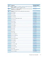
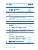
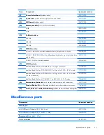
background image

Battery

Description

Spare part number

6 cell, 44-Wh, 1.98-Ah, Li-ion battery

698943-001

Before disassembling the computer, follow these steps:

1.

Turn off the computer. If you are unsure whether the computer is off or in Hibernation, turn

the computer on, and then shut it down through the operating system.

2.

Disconnect the power from the computer by unplugging the power cord from the computer.

3.

Disconnect all external devices from the computer.
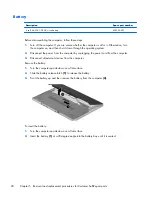
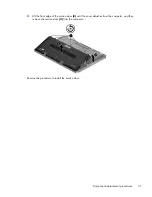
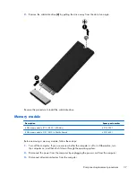
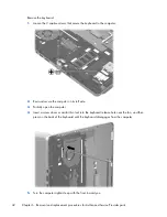
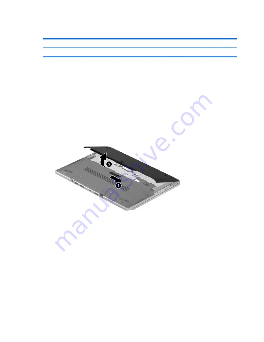
Remove the battery:

1.

Turn the computer upside down on a flat surface.

2.

Slide the battery release latch 

(1)

 to release the battery.

3.

Pivot the battery up and then remove the battery from the computer 

(2)

.

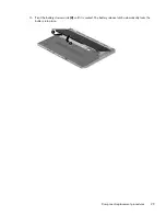
To insert the battery:

1.

Turn the computer upside down on a flat surface.

2.

Insert the battery 

(1)

 at a 45-degree angle into the battery bay until it is seated.

28

Chapter 5   Removal and replacement procedures for Customer Self-Repair parts

Summary of Contents for EliteBook Revolve 810 G2 Tablet

Page 1: ...HP EliteBook Revolve 810 G2 Maintenance and Service Guide ...

Page 2: ...t all features are available in all editions of Windows 8 This computer may require upgraded and or separately purchased hardware drivers and or software to take full advantage of Windows 8 functionality See http www microsoft com for details The information contained herein is subject to change without notice The only warranties for HP products and services are set forth in the express warranty s...

Page 3: ...hat should only be accessed by an authorized service provider See Chapter 5 Removal and replacement procedures for Customer Self Repair parts for details Accessing parts described in Chapter 6 Removal and replacement procedures for Authorized Service Provider only parts can damage the computer or void your warranty iii ...

Page 4: ...iv Important Notice about Customer Self Repair Parts ...

Page 5: ...ow another hard surface such as an adjoining optional printer or a soft surface such as pillows or rugs or clothing to block airflow Also do not allow the AC adapter to contact the skin or a soft surface such as pillows or rugs or clothing during operation The device and the AC adapter comply with the user accessible surface temperature limits defined by the International Standard for Safety of In...

Page 6: ...vi Safety warning notice ...

Page 7: ... listing 18 4 Removal and replacement procedures preliminary requirements 22 Tools required 22 Service considerations 22 Plastic parts 22 Cables and connectors 23 Drive handling 23 Grounding guidelines 24 Electrostatic discharge damage 24 Packaging and transporting guidelines 25 Workstation guidelines 25 Equipment guidelines 26 5 Removal and replacement procedures for Customer Self Repair parts 27...

Page 8: ...the Windows recovery tools 63 Using f11 recovery tools 63 Using Windows operating system media purchased separately 64 Using Windows Refresh or Windows Reset 65 Using HP Software Setup 65 Windows 7 66 Creating recovery media and backups 66 Guidelines 66 Creating recovery media with HP Recovery Disc Creator select models only 66 Creating recovery media 67 Backing up your information 67 Performing a...

Page 9: ...are Diagnostics UEFI 76 Starting Setup Utility BIOS 76 Updating the BIOS 76 Determining the BIOS version 76 Downloading a BIOS update 77 Using HP PC Hardware Diagnostics UEFI select models only 77 Downloading HP PC Hardware Diagnostics UEFI to a USB device 78 10 Specifications 79 Computer specifications 79 11 6 inch UWVA display specifications 80 11 Power cord set requirements 81 Requirements for ...

Page 10: ...x ...

Page 11: ...h definition HD light emitting diode LED AntiGlare AG UWVA 1366 768 ultraslim display with webcam and microphone Touchscreen enabled Touch Controller Atmel 2952T1 Typical brightness 400 nits Memory One customer accessible upgradable memory module slot 4 GB on the system board Support for DDR3L PC 3 12800 1600 MHz Support for 12288 MB of system RAM in the following configurations 12288 MB 8192 MB m...

Page 12: ...etwork WWAN options by way of wireless module Support for the following WWAN modules HP hs3110 HSPA Mobile Broadband HP lt4111 LTE EV DO HSPA Mobile Broadband Module for use in the United States HP lt4112 LTE HSPA Mobile Broadband Module for use in Europe and Asia Pacific WWAN secured by micro SIM Support for no WWAN option Support for WWAN after market option Integrated near field communication N...

Page 13: ...er cord options see Miscellaneous parts on page 17 Support for 6 cell 44 Wh 1 98 Ah Li ion battery Li ion Security Support for security cable lock Support for Trusted Platfom Module TPM 1 2 Enhanced Drive Lock HP ProtectTools Limited Suite HP Power Assistant Preboot Authentication Password Operating system Preinstalled Windows 8 1 CH 64 bit only available in China Windows 8 1 EM 64 bit Windows 8 1...

Page 14: ...2 External component identification 4 Chapter 2 External component identification ...

Page 15: ...y over the keyboard To change the tablet back into a notebook reverse these steps Display Component Description 1 WWAN antennas 2 Send and receive wireless signals to communicate with wireless wide area networks WWAN 2 Ambient light sensor Brightens or dims the display in response to ambient light 3 WLAN antennas 2 Send and receive wireless signals to communicate with wireless local area networks ...

Page 16: ...escription 1 Power button Turns power on and off 2 Power light On The computer is on Blinking The computer is in the Sleep state a powersaving state The computer shuts off power to the display and other unneeded components The computer is off or in Hibernation Hibernation is a power saving state that uses the least amount of power 3 Rotation lock Locks screen orientation in either Landscape or Por...

Page 17: ...ected to the jack the computer speakers are disabled NOTE Be sure that the device cable has a 4 conductor connector that supports both audio out headphone and audio in microphone 9 Docking port Connects an optional docking device Left side NOTE Your computer may look slightly different from the illustration in this section Component Description 1 Vent Enables airflow to cool internal components NO...

Page 18: ...n on an external mouse 4 Right TouchPad button Functions like the right button on an external mouse Lights NOTE Your computer may look slightly different from the illustration in this section Component Description 1 Caps lock light On Caps lock is on which switches the keys to all capital letters 2 Mute light Amber Computer sound is off Off Computer sound is on 8 Chapter 2 External component ident...

Page 19: ...TouchPad light On The TouchPad is off Off The TouchPad is on Keys NOTE Your computer may look slightly different from the illustration in this section Component Description 1 esc key Displays system information when pressed in combination with the fn key 2 fn key Executes frequently used system functions when pressed in combination with a function key the num lk key the esc key or the b key 3 Wind...

Page 20: ...rned on it can be used like an external numeric keypad Each key on the keypad performs the function indicated by the icon in the upper right corner of the key 6 Windows application key Displays options for a selected object 10 Chapter 2 External component identification ...

Page 21: ...ental agency that regulates wireless devices in your country or region 2 Vents Enables airflow to cool internal components NOTE The computer fan starts up automatically to cool internal components and prevent overheating It is normal for the internal fan to cycle on and off during routine operation 3 Near Field Communication NFC antenna Allows you to connect wirelessly with communicate with and tr...

Page 22: ...ent the computer from being mishandled or stolen 4 DisplayPort Connects an optional digital display device such as a high performance monitor or projector 5 USB 3 0 charging port Connects an optional USB device such as a keyboard mouse external drive printer scanner or USB hub Standard USB ports will not charge all USB devices or will charge using a low current Some USB devices require power and r...

Page 23: ...ixed to the front of the computer 2 Serial number s n This is an alphanumeric identifier that is unique to each product 3 Part number Product number p n This number provides specific information about the product s hardware components The part number helps a service technician to determine what components and parts are needed 4 Warranty period This number describes the duration of the warranty per...

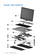
Page 24: ...Computer major components 14 Chapter 3 Illustrated parts catalog ...

Page 25: ...rk 716747 081 For use in France 716747 051 For use in Germany 716747 041 For use in Greece 716747 151 For use in Hungary 716747 211 For use in Iceland 716747 DD1 For use in India 716747 D61 For use in Israel 716747 BB1 For use in Italy 716747 061 For use in Japan 716747 291 For use in Latin America 716747 161 For use in the Netherlands 716747 B31 For use in Norway 716747 091 For use in Northwest A...

Page 26: ...d with an Intel Dual Core i5 4300U 1 9 GHz processor turbo up to 2 90 GHz 1600 MHz FSB 3 MB L3 cache 15 W and the Windows 8 Professional operating system 753725 601 Equipped with an Intel Dual Core i5 4200U 1 6 GHz processor turbo up to 2 6 GHz 1600 MHz FSB 3 MB L3 cache 15 W and the Standard operating system 753724 001 Equipped with an Intel Dual Core i5 4200U 1 6 GHz processor turbo up to 2 6 GH...

Page 27: ... 802 11 a b g n 2x2 WiFi 717380 001 Intel Dual Band Wireless N 7260AN 802 11 a b g n 2x2 WiFi BT 4 0 combo 717379 001 Intel Dual Band Wireless N 7260AN 802 11 a b g n 2x2 WiFi BT 4 0 combo for use in Indonesia 747833 001 Intel Dual Band Wireless AC 7260 802 11 ac 2x2 WiFi BT 4 0 combo 710663 001 16 Service door plastics kit not illustrated includes screws and 2 rubber feet 753713 001 Plastics Rubb...

Page 28: ...rt number listing Spare part number Description 490371 001 Power cord for use in North America 3 pin black 1 83 m 490371 011 Power cord for use in Australia 3 pin black 1 83 m 490371 021 Power cord for use in Europe 3 pin black 1 83 m 490371 031 Power cord for use in the United Kingdom and Singapore 3 pin black 1 83 m 490371 061 Power cord for use in Italy 3 pin black 1 83 m 490371 081 Power cord ...

Page 29: ...s backlight cable and keyboard cable 716747 051 Keyboard with backlight for use in Germany includes backlight cable and keyboard cable 716747 061 Keyboard with backlight for use in Italy includes backlight cable and keyboard cable 716747 071 Keyboard with backlight for use in Spain includes backlight cable and keyboard cable 716747 081 Keyboard with backlight for use in Denmark includes backlight ...

Page 30: ...47 DB1 Keyboard with backlight for use in Canada includes backlight cable and keyboard cable 716747 DD1 Keyboard with backlight for use in Canada includes backlight cable and keyboard cable 716747 FL1 Keyboard with backlight for use in the Czech Republic and Slovakia includes backlight cable and keyboard cable 716747 FP1 Keyboard with backlight for use in Northwest Africa includes backlight cable ...

Page 31: ...MHz FSB 3 MB L3 cache 15 W and the Windows 8 1 Professional operating system includes processor and replacement thermal material 753725 001 System board equipped with an Intel Dual Core i5 4300U 1 9 GHz processor turbo up to 2 90 GHz 1600 MHz FSB 3 MB L3 cache 15 W and the Standard operating system includes processor and replacement thermal material 753725 501 System board equipped with an Intel D...

Page 32: ...ing sections include some of the considerations that you must keep in mind during disassembly and assembly procedures NOTE As you remove each subassembly from the computer place the subassembly and all accompanying screws away from the work area to prevent damage Plastic parts CAUTION Using excessive force during disassembly and reassembly can damage plastic parts Use care when handling the plasti...

Page 33: ...nserting a hard drive shut down the computer If you are unsure whether the computer is off or in Hibernation turn the computer on and then shut it down through the operating system Before handling a drive be sure that you are discharged of static electricity While handling a drive avoid touching the connector Before removing a diskette drive or optical drive be sure that a diskette or disc is not ...

Page 34: ... components in their electrostatic safe containers until you are ready to install them Before touching an electronic component discharge static electricity by using the guidelines described in this section Avoid touching pins leads and circuitry Handle electronic components as little as possible If you remove a component place it in an electrostatic safe container The following table shows how hum...

Page 35: ... to ground and that proper materials are selected to avoid static charging When grounding is not possible use an ionizer to dissipate electric charges Workstation guidelines Follow these grounding workstation guidelines Cover the workstation with approved static shielding material Use a wrist strap connected to a properly grounded work surface and use properly grounded tools and equipment Use cond...

Page 36: ...operator and ground To be effective the conductive must be worn in contact with the skin The following grounding equipment is recommended to prevent electrostatic damage Antistatic tape Antistatic smocks aprons and sleeve protectors Conductive bins and other assembly or soldering aids Nonconductive foam Conductive tabletop workstations with ground cords of one megohm resistance Static dissipative ...

Page 37: ...follow the procedures described here to access and replace Customer Self Repair parts successfully NOTE Details about your computer including model serial number product key and length of warranty are on the service tag at the bottom of your computer This chapter provides removal and replacement procedures for Customer Self Repair parts There are as many as 11 screws that must be removed replaced ...

Page 38: ...ter by unplugging the power cord from the computer 3 Disconnect all external devices from the computer Remove the battery 1 Turn the computer upside down on a flat surface 2 Slide the battery release latch 1 to release the battery 3 Pivot the battery up and then remove the battery from the computer 2 To insert the battery 1 Turn the computer upside down on a flat surface 2 Insert the battery 1 at ...

Page 39: ...3 Pivot the battery downwards 2 until it is seated The battery release latch automatically locks the battery into place Component replacement procedures 29 ...

Page 40: ...service door 1 Turn the computer upside down with the front toward you 2 Press on the memory card bezel 1 once to release the bezel and then press on the bezel again to remove the bezel 3 Remove the two large rubber screw covers 2 4 Remove the two Phillips M2 0 6 5 screws 3 that secure the service door to the computer 5 Remove the two small rubber screw covers 4 The large and small rubber screw co...

Page 41: ...ront edge of the service door 2 until the cover detaches from the computer and then remove the service door 3 from the computer Reverse this procedure to install the service door Component replacement procedures 31 ...

Page 42: ...ollow these steps 1 Turn off the computer If you are unsure whether the computer is off or in Hibernation turn the computer on and then shut it down through the operating system 2 Disconnect the power from the computer by unplugging the power cord from the computer 3 Disconnect all external devices from the computer 4 Remove the battery see Battery on page 28 5 Remove the service door see Service ...

Page 43: ...e NOTE If the WWAN antenna cables are not connected to the terminals on the WWAN module the protective sleeves must be installed on the antenna connectors as shown in the following illustration Reverse this procedure to install the WWAN module Component replacement procedures 33 ...

Page 44: ... removing the WLAN module follow these steps 1 Turn off the computer If you are unsure whether the computer is off or in Hibernation turn the computer on and then shut it down through the operating system 2 Disconnect the power from the computer by unplugging the power cord from the computer 3 Disconnect all external devices from the computer 4 Remove the battery see Battery on page 28 5 Remove th...

Page 45: ...are not connected to the terminals on the WLAN module the protective sleeves should be installed on the antenna connectors as shown in the following illustration Reverse this procedure to install the WLAN module Solid state drive Description Spare part number 256 GB 753729 001 Component replacement procedures 35 ...

Page 46: ...g system 2 Disconnect the power from the computer by unplugging the power cord from the computer 3 Disconnect all external devices from the computer 4 Remove the battery see Battery on page 28 5 Remove the service door see Service door on page 30 Remove the solid state drive 1 Remove the Phillips M2 0 3 0 screw 1 that secures the solid state drive to the computer The solid state drive tilts up 36 ...

Page 47: ...B memory module PC3L 12800 1600Mhz Shared 693374 001 Before removing a memory module follow these steps 1 Turn off the computer If you are unsure whether the computer is off or in Hibernation turn the computer on and then shut it down through the operating system 2 Disconnect the power from the computer by unplugging the power cord from the computer 3 Disconnect all external devices from the compu...

Page 48: ...t install the new memory module in the same slot 1 Spread the two retaining tabs 1 on each side of the memory module slot to release the memory module The memory module tilts up 2 Remove the memory module 2 by pulling it away from the slot at a 45 degree angle Reverse this procedure to install the memory module 38 Chapter 5 Removal and replacement procedures for Customer Self Repair parts ...

Page 49: ...puter including model serial number product key and length of warranty are on the service tag at the bottom of your computer See Bottom on page 11 for details This chapter provides removal and replacement procedures for Authorized Service Provider only parts There are as many as 62 screws that must be removed replaced and or loosened when servicing Authorized Service Provider only parts Make speci...

Page 50: ...ve the service door see Service door on page 30 Remove the NFC board 1 Disconnect the NFC antenna cable 1 from the NFC board The NFC antenna cable is included in the Top cover spare part kit spare part number 2 Release the zero insertion force ZIF connector 2 to which the NFC board cable is attached and then disconnect the NFC board cable from the system board 3 Remove the Phillips M1 5 2 0 screw ...

Page 51: ...ungary 716747 211 For use in Sweden and Finland 716747 B71 For use in Iceland 716747 DD1 For use in Switzerland 716747 BG1 For use in India 716747 D61 For use in Taiwan 716747 AB1 For use in Israel 716747 BB1 For use in Thailand 716747 281 For use in Italy 716747 061 For use in Turkey 716747 141 For use in Japan 716747 291 For use in the United Kingdom and Singapore 716747 031 For use in Latin Ame...

Page 52: ...ally open the computer 4 Insert a screw driver or similar thin tool into the keyboard release hole near the fan and then press on the back of the keyboard until the keyboard disengages from the computer 5 Turn the computer right side up with the front toward you 42 Chapter 6 Removal and replacement procedures for Authorized Service Provider parts ...

Page 53: ...own on the palm rest 8 Release the ZIF connector 1 to which the backlight cable is attached and then disconnect the backlight cable 2 from the system board 9 Release the ZIF connector 3 to which the keyboard cable is attached and then disconnect the keyboard cable 4 from the system board Component replacement procedures 43 ...

Page 54: ...10 Remove the keyboard 5 Reverse this procedure to install the keyboard 44 Chapter 6 Removal and replacement procedures for Authorized Service Provider parts ...

Page 55: ...ting system 2 Disconnect the power from the computer by unplugging the power cord from the computer 3 Disconnect all external devices from the computer 4 Remove the battery see Battery on page 28 5 Remove the service door see Service door on page 30 6 Remove the keyboard see Keyboard on page 41 Remove the Top cover 1 Remove the two Phillips M2 0 4 3 screws that secure the Top cover to the computer...

Page 56: ...N antenna cables and the WLAN antenna cables 6 Remove the five Torx T8M2 0 5 65 screws 1 and the Torx T8M2 0 2 5 screw 2 that secure the Top cover to the computer 46 Chapter 6 Removal and replacement procedures for Authorized Service Provider parts ...

Page 57: ...7 Remove the Top cover Reverse this procedure to install the Top cover Component replacement procedures 47 ...

Page 58: ... from the computer 3 Disconnect all external devices from the computer 4 Remove the battery see Battery on page 28 and then remove the following components a service door see Service door on page 30 b Keyboard see Keyboard on page 41 c Top cover see Top cover on page 45 Remove the speakers 1 Disconnect the speaker cables 1 from the system board 2 Release the left speaker cable 2 from the clips bui...

Page 59: ...4 Remove the speakers 4 Reverse this procedure to install the speakers Component replacement procedures 49 ...

Page 60: ...4 Remove the battery see Battery on page 28 and then remove the following components a Service door see Service door on page 30 b Keyboard see Keyboard on page 41 c Top cover see Top cover on page 45 d Right speaker see Speakers on page 48 Remove the button board 1 Turn the computer right side up with the front toward you 2 Open the computer 3 Release the ZIF connector 1 to which the button board ...

Page 61: ...low these steps 1 Turn off the computer If you are unsure whether the computer is off or in Hibernation turn the computer on and then shut it down through the operating system 2 Disconnect the power from the computer by unplugging the power cord from the computer 3 Disconnect all external devices from the computer 4 Remove the battery see Battery on page 28 and then remove the following components...

Page 62: ...p cover The RTC battery is attached to the system board with double sided tape 3 Remove the RTC battery Reverse this procedure to install the RTC battery 52 Chapter 6 Removal and replacement procedures for Authorized Service Provider parts ...

Page 63: ... page 28 and then remove the following components a Service door see Service door on page 30 b Keyboard see Keyboard on page 41 c Top cover see Top cover on page 45 Remove the fan heat sink assembly 1 Disconnect the fan cable 1 from the system board 2 Following the 1 2 3 4 sequence stamped into the fan heat sink assembly loosen the four captive Phillips M2 0 6 5 screws 2 that secure the fan heat s...

Page 64: ...oved Replacement thermal material is included with the fan heat sink assembly and system board spare part kits Thermal paste is used on the processor 1 and the section of the fan heat sink assembly 2 that services it Reverse this procedure to install the fan heat sink assembly 54 Chapter 6 Removal and replacement procedures for Authorized Service Provider parts ...

Page 65: ...U 1 6 GHz processor turbo up to 2 6 GHz 1600 MHz FSB 3 MB L3 cache 15 and the Windows 8 Standard operating system 753724 501 Equipped with an Intel Dual Core i5 4200U 1 6 GHz processor turbo up to 2 6 GHz 1600 MHz FSB 3 MB L3 cache 15 and the Windows 8 Professional operating system 753724 601 Equipped with an Intel Dual Core i3 4010U 1 7 GHz processor 1600 MHz front side bus FSB 3 MB L3 cache 15 W...

Page 66: ...ry module on page 37 RTC battery see RTC battery on page 51 Remove the system board 1 Turn the computer right side up with the front toward you 2 Open the computer 3 Release the ZIF connector 1 to which the TouchPad cable is attached and then disconnect the TouchPad cable 2 from the system board 4 Disconnect the display panel cable 1 from the system board 5 Remove the Phillips M2 0 2 5 screw 2 tha...

Page 67: ...6 Remove the system board 3 Reverse this procedure to install the system board Component replacement procedures 57 ...

Page 68: ...s from the computer 4 Remove the battery see Battery on page 28 and then remove the following components a Service door see Service door on page 30 b WWAN module see WWAN module on page 32 c WLAN module see WLAN module on page 34 d Solid state drive see Solid state drive on page 35 e Keyboard see Keyboard on page 41 f Top cover see Top cover on page 45 g Fan heat sink assembly see Fan heat sink as...

Page 69: ... computer 5 Rotate the display assembly 1 clockwise until it is perpendicular to the computer body 6 Detach the left 2 and right edges of the hinge cover from the computer 7 Remove the hinge cover 3 by sliding it away from the computer 8 Remove the hinge cap 4 Reverse this procedure to install the hinge cover and hinge cap Component replacement procedures 59 ...

Page 70: ...ttery on page 28 and then remove the following components a Service door see Service door on page 30 b WWAN module see WWAN module on page 32 c WLAN module see WLAN module on page 34 d Solid state drive see Solid state drive on page 35 e Keyboard see Keyboard on page 41 f Top cover see Top cover on page 45 g Fan heat sink assembly see Fan heat sink assembly on page 53 h System board see System boa...

Page 71: ...2 Slide the display assembly 2 away from the top cover and remove it Reverse this procedure to install the display assembly Component replacement procedures 61 ...

Page 72: ...backup immediately after initial system setup As you add new software and data files you should continue to back up your system on a regular basis to maintain a reasonably current backup The system repair media select models only are used to start up boot the computer and repair the operating system in case of system instability or failure Your initial and subsequent backups allow you to restore y...

Page 73: ...puter by pressing and holding the shift key while clicking Restart 4 Select Troubleshoot select Advanced Options and then select Startup Repair 5 Follow the on screen instructions NOTE For additional information on recovering information using the Windows tools perform a search for these topics in Windows Help and Support Using f11 recovery tools CAUTION Using f11 completely erases hard drive cont...

Page 74: ...eated and any software that you have installed on the computer are permanently removed When reformatting is complete the recovery process helps you restore the operating system as well as drivers software and utilities To initiate a full install of the operating system using a Windows operating system DVD NOTE This process takes several minutes 1 If possible back up all personal files 2 Insert the...

Page 75: ...tting of your computer or remove personal information before you give away or recycle your computer For more information on these features see Windows Help and Support Using HP Software Setup HP Software Setup can be used to reinstall drivers or select software that has been corrupted or deleted from the system 1 From the Start screen type HP Software Setup 2 Open HP Software Setup 3 Follow the on...

Page 76: ...ed optical drive select models only or an optional external optical drive Create system restore points NOTE This guide describes an overview of backing up restoring and recovering options For more details about the tools provided see Help and Support To access Help and Support select Start Help and Support NOTE HP recommends that you print the recovery procedures and save them for later use in cas...

Page 77: ...ton to start the burning process Backing up your information You should create system repair media and your initial backup immediately after initial system setup As you add new software and data files you should continue to back up your system on a regular basis to maintain a reasonably current backup You should also create Windows system repair media select models only which can be used to start ...

Page 78: ...very In case of system failure or instability the computer provides the following tools to recover your files Windows recovery tools You can use Windows Backup and Restore to recover information you have previously backed up You can also use Windows Startup Repair to fix problems that might prevent Windows from starting correctly f11 recovery tools select models only You can use the f11 recovery t...

Page 79: ...o recover your information using Startup Repair follow these steps CAUTION Some Startup Repair options will completely erase and reformat the hard drive All files you have created and any software installed on the computer are permanently removed When reformatting is complete the recovery process restores the operating system as well as the drivers software and utilities from the backup used for r...

Page 80: ...e on screen instructions Using Windows 7 operating system media If you cannot use the recovery media you previously created using the HP Recovery Disc Creator select models only you must purchase a Windows 7 operating system DVD to reboot the computer and repair the operating system To order a Windows 7 operating system DVD go to the HP website For U S support go to http www hp com support For wor...

Page 81: ...the on screen instructions After the repair is completed 1 Eject the Windows 7 operating system DVD and then insert the Driver Recovery DVD 2 Install the Hardware Enabling Drivers first and then install Recommended Applications Windows 7 71 ...

Page 82: ... key for Startup Menu message is displayed at the bottom of the screen 2 Press f10 to enter Computer Setup Navigating and selecting in Computer Setup To navigate and select in Computer Setup follow these steps 1 Turn on or restart the computer and then press esc while the Press the ESC key for Startup Menu message is displayed at the bottom of the screen To select a menu or a menu item use the tab...

Page 83: ...tory follow these steps 1 Turn on or restart the computer and then press esc while the Press the ESC key for Startup Menu message is displayed at the bottom of the screen 2 Press f10 to enter Computer Setup 3 Use a pointing device or the arrow keys to select File Restore Defaults 4 Follow the on screen instructions 5 To save your changes and exit click the Save icon in the lower left corner of the...

Page 84: ...e computer by unplugging the power cord from the AC outlet Do not shut down the computer or initiate Sleep Do not insert remove connect or disconnect any device cable or cord 1 From the Start screen select the HP Support Assistant app 2 Select Updates and tune ups and then select Check for HP updates now 3 At the download area follow these steps a Identify the BIOS update that is later than the BI...

Page 85: ...est does not detect Hard disk test This test analyzes the physical condition of the hard drive and then checks all data in every sector of the hard drive If the test detects a damaged sector it attempts to move the data to a good sector Memory test This test analyzes the physical condition of the memory modules If it reports an error replace the memory modules immediately Battery test This test an...

Page 86: ...e on the HP website Most BIOS updates on the HP website are packaged in compressed files called SoftPaqs Some download packages contain a file named Readme txt which contains information regarding installing and troubleshooting the file Determining the BIOS version To determine whether available BIOS updates contain later BIOS versions than those currently installed on the computer you need to kno...

Page 87: ...on to the hard drive Make a note of the path to the location on your hard drive where the BIOS update is downloaded You will need to access this path when you are ready to install the update NOTE If you connect your computer to a network consult the network administrator before installing any software updates especially system BIOS updates BIOS installation procedures vary Follow any instructions ...

Page 88: ...select the type of diagnostic test you want to run and then follow the on screen instructions NOTE If you need to stop a diagnostic test while it is running press esc Downloading HP PC Hardware Diagnostics UEFI to a USB device NOTE Instructions for downloading HP PC Hardware Diagnostics UEFI are provided in English only 1 Go to http www hp com 2 Point to Support located at the top of the page and ...

Page 89: ... 65 W 19 5 Vdc 4 74 A 90 W 19 5 Vdc 4 82 A 90 W 19 5Vdc 2 31A 45 W Temperature Operating 5 C to 35 C 41 F to 95 F Nonoperating 20 C to 60 C 4 F to 140 F Relative humidity noncondensing Operating 10 to 90 Nonoperating 5 to 95 Maximum altitude unpressurized Operating 15 m to 3 048 m 50 ft to 10 000 ft Nonoperating 15 m to 12 192 m 50 ft to 40 000 ft NOTE Applicable product safety standards specify t...

Page 90: ... Number of colors Up to 16 8 million Contrast ratio 200 1 typical Brightness 400 nits typical Pixel resolution Pitch 0 197 0 197 mm Format 1366 768 Configuration RGB vertical stripe Backlight LED backlit Character display 80 25 Total power consumption 3 46 W Viewing angle 65 horizontal 50 vertical typical 80 Chapter 10 Specifications ...

Page 91: ... m 6 ft All power cord sets must be approved by an acceptable accredited agency responsible for evaluation in the country or region where the power cord set will be used The power cord sets must have a minimum current capacity of 10 amps and a nominal voltage rating of 125 or 250 V AC as required by the power system of each country or region The appliance coupler must meet the mechanical configura...

Page 92: ...ance coupler flexible cord and wall plug must bear a T mark and registration number in accordance with the Japanese Dentori Law The flexible cord must be Type VCT or VCTF 3 conductor 1 00 mm conductor size The wall plug must be a two pole grounding type with a Japanese Industrial Standard C8303 7 A 125 V configuration 4 The flexible cord must be Type RVV 3 conductor 0 75 mm conductor size Power co...

Page 93: ...he battery in general household waste Follow the local laws and regulations in your area for battery disposal HP encourages customers to recycle used electronic hardware HP original print cartridges and rechargeable batteries For more information about recycling programs see the HP Web site at http www hp com recycle 83 ...

Page 94: ...y components 5 specifications 80 display assembly removal 60 spare part number 15 21 60 display panel product description 1 DisplayPort 12 docking port 7 docking product description 2 Driver Recovery DVD creating 66 E esc key 9 Ethernet product description 1 F f11 recovery 63 fan heat sink assembly removal 53 spare part number 16 20 53 fn key 9 function keys 9 G graphics product description 1 H ha...

Page 95: ...e 1 video 1 wireless 2 product name 1 R rear components 12 recovery 65 recovery media creating 66 recovery partition 63 refresh 65 removal replacement procedures 27 39 restoring the hard drive 63 right side components 6 RJ 45 network jack 12 rotation lock button 6 RTC battery removal 51 spare part number 16 19 51 rubber screw cover removal 30 S Screw Kit spare part number 18 21 security cable slot...

Page 96: ...cation key 10 Windows button 9 Windows Home button 6 wireless antenna location 5 wireless light 9 wireless product description 2 WLAN spare part numbers 19 20 WLAN module removal 34 spare part numbers 17 34 WWAN spare part numbers 19 20 WWAN module removal 32 spare part numbers 17 32 86 Index ...

Reviews: