1.
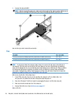
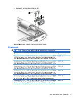
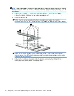
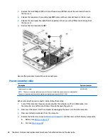
Remove the two Phillips PM2.0×2.2 broad head screws (1) that secure the card reader board to
the top cover.
2.
Release the two pieces of grounding tape (2) that secure the card reader board to the top cover.
3.
Release the card reader board (3) from the opening in the top cover by lifting it up and away from
the top cover.
4.
Remove the card reader board (4).
Reverse this procedure to install the card reader board.
Power connector cable
Description
Spare part number
Power connector cable
NOTE:
The power connector cable spare part kit does not include the power connector cable bracket.
The power connector cable bracket is available using spare part number 818117-001.
818108-001
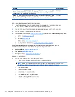
Before removing the power connector cable, follow these steps:
1.
Turn off the computer. If you are unsure whether the computer is off or in Hibernation, turn
the computer on, and then shut it down through the operating system.
2.
Disconnect the power from the computer by unplugging the power cord from the computer.
3.
Disconnect all external devices from the computer.
4.
Remove the bottom cover (see
Bottom cover on page 27
), and then remove the following components:
a.
Battery (see
Battery on page 37
)
b.
Fan (see
Fan on page 46
)
60
Chapter 6 Removal and replacement procedures for Authorized Service Provider parts

