background image

4.

Double-click the file that has an .exe extension (for example, 

filename

.exe).

The BIOS installation begins.

5.

Complete the installation by following the on-screen instructions.

NOTE:

After a message on the screen reports a successful installation, you can delete the

downloaded file from your hard drive.

Using System Diagnostics

System Diagnostics allows you to run diagnostic tests to determine if the computer hardware is

functioning properly. The following diagnostic tests are available in System Diagnostics:

Start-up test—This test analyzes the main computer components that are required to start

the computer.

Run-in test—This test repeats the start-up test and checks for intermittent problems that the start-up

test does not detect.

Hard disk test—This test analyzes the physical condition of the hard drive, and then checks all

data in every sector of the hard drive. If the test detects a damaged sector, it attempts to move the

data to a good sector.

Memory test—This test analyzes the physical condition of the memory modules. If it reports an

error, replace the memory modules immediately.

Battery test—This test analyzes the condition of the battery. If the battery fails the test, contact HP

support to report the issue and purchase a replacement battery.

You can also view system information and error logs in the System Diagnostics window.

To start System Diagnostics:

1.

Turn on or restart the computer. While the “Press the ESC key for Startup Menu” message is

displayed in the lower-left corner of the screen, press 

esc

. When the Startup Menu is displayed,

press 

f2

.

2.

Click the diagnostic test you want to run, and then follow the on-screen instructions.

NOTE:

If you need to stop a diagnostics test while it is running, press 

esc

.

Using System Diagnostics

73

Summary of Contents for ENVY m6 Sleekbook

Page 1: ...HP ENVY m6 Sleekbook HP ENVY Touchsmart m6 SleekBook HP ENVY TouchSmart m6 Ultrabook Maintenance and Service Guide IMPORTANT This document is intended for HP authorized service providers only ...

Page 2: ...oft Corporation SD Logo is a trademark of its proprietor The information contained herein is subject to change without notice The only warranties for HP products and services are set forth in the express warranty statements accompanying such products and services Nothing herein should be construed as constituting an additional warranty HP shall not be liable for technical or editorial errors or om...

Page 3: ...w another hard surface such as an adjoining optional printer or a soft surface such as pillows or rugs or clothing to block airflow Also do not allow the AC adapter to contact the skin or a soft surface such as pillows or rugs or clothing during operation The device and the AC adapter comply with the user accessible surface temperature limits defined by the International Standard for Safety of Inf...

Page 4: ...iv Safety warning notice ...

Page 5: ...puter major components 17 Display assembly subcomponents 21 Miscellaneous parts 22 Sequential part number listing 22 4 Removal and replacement procedures 25 Preliminary replacement requirements 25 Tools required 25 Service considerations 25 Plastic parts 25 Cables and connectors 25 Drive handling 26 Grounding guidelines 26 Electrostatic discharge damage 26 Packaging and transporting guidelines 28 ...

Page 6: ...ay assembly non touchscreen 58 Display assembly touchscreen 63 5 Setup Utility BIOS and System Diagnostics 69 Using Setup Utility 69 Starting Setup Utility 69 Changing the language of Setup Utility 69 Navigating and selecting in Setup Utility 70 Displaying system information 70 Restoring factory settings in Setup Utility 71 Exiting Setup Utility 71 Updating the BIOS 71 Determining the BIOS version...

Page 7: ...y tools 78 Using Windows 8 operating system media purchased separately 79 Using Windows Refresh for quick and easy recovery 80 Remove everything and reinstall Windows 80 Using HP Software Setup 81 8 Power cord set requirements 82 Requirements for all countries 82 Requirements for specific countries and regions 83 9 Recycling 85 Index 86 vii ...

Page 8: ...viii ...

Page 9: ...B L2 DDR3L 1333MH Quad 25W Chipset Intel Lynx Point LP PCH Integrated in MCP AMD A76M FCH Graphics Intel HD Graphics 5000 and Intel HD Graphics 4400 Supports HP Decode DX11 and HDMI AMD Radeon HD 8610G graphics Supports DX11 HD Decoder and HDMI and PX 7 0 Panels 39 6 mm 15 6 inch HD LED BrightView 1366x768 Slim 3 2mm SVA Color Gamut 45 200 nits 39 6 mm 15 6 inch FHD WLED BrightView 1920x1080 Slim ...

Page 10: ...096 MB x 1 4096 MB 4096 MB x 1 Drives Supports single 7 9 5mm SATA 2 5 HDD with Accelerometer HDD protection support 500 GB 5400 rpm 7 mm 750 GB 5400 rpm 9 5 mm 1 TB 5400 rpm 9 5 mm Supports mSATA SSD configurations with Intel Smart Response Technology SRT support 24 GB mSATA SSD 32 GB mSATA SSD 128 GB mSATA SSD Audio and video Dual array digital microphones Subwoofer Beats audio dual speakers HD ...

Page 11: ... formats Ralink RT3290LE 802 11bgn 1x1 Wi Fi BT 4 0 Combo Adapter Qualcomm QCA9565 802 11bgn 1x1 Wi Fi BT4 0 Combo Adapter External media card Push push insertion removal HP Multi Format Media Reader supports the following digital card formats Secure Digital SD Card Secure Digital High Capacity SDHC Card Secure Digital Extended Capacity SDxC Card HP Multi Format Media Reader supports the following...

Page 12: ...land style keyboard with numeric keypad TouchPad with multi touch gestures and image sensors Support Windows 8 Modern TouchPad Gestures Taps enabled as default Power requirements Supports the following HP AC adapters 65W 4 5mm connector Smart Pin 65W 4 5mm connector Smart Pin EM 65W 4 5mm connector Smart Pin MSG Supports the following batteries 3 Cell battery 50Whr 4 56AH Polymer Security Kensingt...

Page 13: ... models AMD models Operating system Preinstalled Windows 8 1 64 bit Windows 8 64 bit Windows 8 Standard Windows 8 Professional Serviceability End user replaceable parts Memory Hard drive AC adapter Battery MiniCard components 5 ...

Page 14: ...use Off The webcam is not in use 3 HP TrueVision HD Webcam Records video captures still photographs and provides access to video conferences and online chat by means of streaming video To use the webcam from the Start screen type c and then select CyberLink YouCam from the list of applications 6 Chapter 2 External component identification ...

Page 15: ... connect to the Internet you need a broadband modem either DSL or cable purchased separately high speed Internet service purchased from an Internet service provider and a wireless router purchased separately The antennas are not visible from the outside of the computer For optimal transmission keep the areas immediately around the antennas free from obstructions For wireless regulatory notices see...

Page 16: ...ects or activates items on the screen NOTE The TouchPad also supports edge swipe gestures 2 Left TouchPad button Functions like the left button on an external mouse 3 Right TouchPad button Functions like the right button on an external mouse 8 Chapter 2 External component identification ...

Page 17: ...f power NOTE For select models the Intel Rapid Start Technology feature is enabled at the factory Rapid Start Technology allows your computer to resume quickly from inactivity 2 Caps lock light On Caps lock is on which switches the keys to all capital letters Off Caps lock is off 3 Mute light Amber Computer sound is off Off Computer sound is on 4 Wireless light White An integrated wireless device ...

Page 18: ...ton will result in the loss of unsaved information If the computer has stopped responding and Microsoft Windows shutdown procedures are ineffective press and hold the power button down for at least 5 seconds to turn off the computer NOTE For select models the Intel Rapid Start Technology feature is enabled at the factory Rapid Start Technology allows your computer to resume quickly from inactivity...

Page 19: ...lock key Controls the function of the integrated numeric keypad Press the key to alternate between the standard numeric function found on an external keypad this function is turned on at the factory and the navigational function indicated by the directional arrows on the keys NOTE The keypad function that is active when the computer is turned off is reinstated when the computer is turned back on 6...

Page 20: ...optional USB device USB charging ports allow you to charge connected USB devices Standard USB ports will not charge all USB devices or will charge using a low current Some USB devices require power and require you to use a powered port NOTE USB charging ports can also charge select models of cell phones and MP3 players even when the computer is off 4 USB 3 0 port Connects an optional USB 3 0 devic...

Page 21: ...the Sleep state which is an energy saving mode The computer shuts off power to the display and other unneeded components Off The computer is off or in Hibernation Hibernation is an energy saving mode that uses the least amount of power NOTE For select models the Intel Rapid Start Technology feature is enabled at the factory Rapid Start Technology allows your computer to resume quickly from inactiv...

Page 22: ...ss this guide from the Start screen type support select the HP Support Assistant app select My computer and then select User guides NOTE When a device is connected to the jack the computer speakers are disabled NOTE Be sure that the device cable has a 4 conductor connector that supports both audio out headphone and audio in microphone 2 USB 2 0 port Connects an optional USB device 3 RJ 45 network ...

Page 23: ...ovides superior bass sound 2 Vents 2 Enable airflow to cool internal components NOTE The computer fan starts up automatically to cool internal components and prevent overheating It is normal for the internal fan to cycle on and off during routine operation Bottom 15 ...

Page 24: ...h product 2 Part number Product number p n This number provides specific information about the product s hardware components The part number helps a service technician determine what components and parts are needed 3 Warranty period This number describes the duration of the warranty period for the computer 4 Model description select models only This is the alphanumeric identifier used to locate do...

Page 25: ...3 Illustrated parts catalog Computer major components Computer major components 17 ...

Page 26: ...10 5745M processor for use in models with non Windows 8 operating systems 725462 001 AMD A10 5745M processor for use in models with the Windows 8 Standard operating system 725462 501 For use in models with Intel processors Intel Core i5 4200U processor for use in models with non Windows 8 operating systems 732775 001 Intel Core i5 4200U processor with the Windows 8 Standard operating system 732775...

Page 27: ...CA9565 802 11bgn 1x1 Wi Fi BT4 0 Combo Adapter 733476 001 For use only in Intel models Intel Dual Band Wireless AC 3160 802 11 a b g n ac 1x1 WiFi with Bluetooth 4 0 combo 710662 001 Intel Centrino Wireless N 2230 802 11bgn 2x2 WiFi BT 4 0 Combo Adapter 717384 005 Mediatek MT7630E 802 11bgn 1x1 Wi Fi BT4 0 Combo Adapter 710418 005 Intel Centrino Wireless N 1030 Bluetooth combo w 2 antennas 802 11 ...

Page 28: ... Intel models 728133 001 For use only in AMD models 727465 001 20 Fan 725445 001 21 RJ 45 cover 727464 001 22 Battery 3 cell 5 0WHr 4 52AH Li ion 715050 001 23 RTC battery 725458 001 24 Service cover 725453 001 20 Chapter 3 Illustrated parts catalog ...

Page 29: ...1 For use in touchscreen models 725449 001 4 Raw display panel 39 6 mm 15 6 inch HD WLED BrightView HD non touch 725454 001 HD touchscreen 725455 001 FHD non touch 725456 001 FHD touchscreen 725457 001 5 WLAN antenna 727460 001 6 Display webcam cable For use in touchscreen models 725443 001 For use in non touch models 725461 001 7 Display enclosure Display assembly subcomponents 21 ...

Page 30: ...e Layer Combo Drive 670290 005 Intel Centrino Wireless N 1030 Bluetooth combo w 2 antennas 802 11 b g n Bluetooth 3 0 for use only in Intel models 676521 005 Hard drive 1 TB 5400 rpm 2 5 in 683802 005 Hard drive 500 GB 5400 rpm 7 mm 690020 005 Ralink Wireless Bluetooth combo w 2 antennas 802 11 b g n Bluetooth 4 0 for use in both Intel and AMD models 691739 005 2 GB memory module PC3L 12800 1600 M...

Page 31: ...nd right brackets hard drive cable and screws 725448 001 Display hinges for use in touchscreen models 725449 001 Display hinges for use in touchscreen models 725450 001 Backlit keyboard for use in the United States 725450 DB1 Backlit keyboard for use in Canada 725451 001 Power button board with cable 725452 001 USB audio board with cable for use in AMD models 725453 001 Service cover 725454 001 Di...

Page 32: ...1 System board for use with computer models equipped with Intel i5 4200U processor and a non Windows 8 operating system 732775 501 System board for use with computer models equipped with Intel i5 4200U processor and the Windows 8 Standard operating system 732775 601 System board for use with computer models equipped with Intel i5 4200U processor and the Windows 8 Professional operating system 7334...

Page 33: ...llowing sections include some of the considerations that you must keep in mind during disassembly and assembly procedures NOTE As you remove each subassembly from the computer place the subassembly and all accompanying screws away from the work area to prevent damage Plastic parts CAUTION Using excessive force during disassembly and reassembly can damage plastic parts Use care when handling the pl...

Page 34: ... covered with at least one inch of shock proof foam Avoid dropping drives from any height onto any surface After removing a hard drive an optical drive or a diskette drive place it in a static proof bag Avoid exposing an internal hard drive to products that have magnetic fields such as monitors or speakers Avoid exposing a drive to temperature extremes or liquids If a drive must be mailed place th...

Page 35: ...The following table shows how humidity affects the electrostatic voltage levels generated by different activities CAUTION A product can be degraded by as little as 700 V Typical electrostatic voltage levels Relative humidity Event 10 40 55 Walking across carpet 35 000 V 15 000 V 7 500 V Walking across vinyl floor 12 000 V 5 000 V 3 000 V Motions of bench worker 6 000 V 800 V 400 V Removing DIPS fr...

Page 36: ...nd that proper materials are selected to avoid static charging When grounding is not possible use an ionizer to dissipate electric charges Workstation guidelines Follow these grounding workstation guidelines Cover the workstation with approved static shielding material Use a wrist strap connected to a properly grounded work surface and use properly grounded tools and equipment Use conductive field...

Page 37: ...ance between the operator and ground To be effective the conductive must be worn in contact with the skin The following grounding equipment is recommended to prevent electrostatic damage Antistatic tape Antistatic smocks aprons and sleeve protectors Conductive bins and other assembly or soldering aids Nonconductive foam Conductive tabletop workstations with ground cords of one megohm resistance St...

Page 38: ...llow these steps 1 Shut down the computer If you are unsure whether the computer is off or in Hibernation turn the computer on and then shut it down through the operating system 2 Disconnect all external devices connected to the computer 3 Disconnect the power from the computer by first unplugging the power cord from the AC outlet and then unplugging the AC adapter from the computer Remove the ser...

Page 39: ...illips screws from the back and the middle of the service cover 3 Lift up the cover 1 from the unit at the rear edge and remove the service cover 2 Reverse this procedure to install the service cover Component replacement procedures 31 ...

Page 40: ...3 Disconnect the power from the computer by first unplugging the power cord from the AC outlet and then unplugging the AC adapter from the computer 4 Remove the service cover see Service cover on page 30 Remove the battery 1 Turn the computer right side up with the front toward you 2 Disconnect the battery cable 1 from the system board 3 Remove the 4 Phillips PM2 5 3 5 screws 2 that secure the bat...

Page 41: ...he AC outlet and then unplugging the AC adapter from the computer 4 Remove the service cover see Service cover on page 30 5 Disconnect the battery cable see Battery on page 32 Remove the RTC battery 1 Disconnect the RTC battery cable from the system board 1 NOTE Use a thin non conductive tool to remove the RTC battery from the socket on the system board 2 Remove the RTC battery 2 The RTC battery i...

Page 42: ...sconnect all external devices connected to the computer 3 Disconnect the power from the computer by first unplugging the power cord from the AC outlet and then unplugging the AC adapter from the computer 4 Remove the service cover see Service cover on page 30 5 Disconnect the battery cable see Battery on page 32 Remove the hard drive 1 Remove the 4 Phillips PM2 5 3 5 screws 1 that secure the hard ...

Page 43: ... steps 1 Turn off the computer If you are unsure whether the computer is off or in Hibernation turn the computer on and then shut it down through the operating system 2 Disconnect the power from the computer by unplugging the power cord from the computer 3 Disconnect all external devices from the computer 4 Remove the service cover see Service cover on page 30 5 Remove the battery see Battery on p...

Page 44: ...2 Remove the solid state drive from the connector 2 Reverse this procedure to install the SSD 36 Chapter 4 Removal and replacement procedures ...

Page 45: ...reless devices in your country or region If you replace the module and then receive a warning message remove the module to restore device functionality and then contact technical support Before removing the WLAN module follow these steps 1 Shut down the computer If you are unsure whether the computer is off or in Hibernation turn the computer on and then shut it down through the operating system 2...

Page 46: ...the module away from the slot at an angle 3 NOTE If the WLAN antennas are not connected to the terminals on the WLAN module the protective sleeves must be installed on the antenna connectors 38 Chapter 4 Removal and replacement procedures ...

Page 47: ...through the operating system 2 Disconnect the power from the computer by unplugging the power cord from the computer 3 Disconnect all external devices from the computer 4 Remove the service cover see Service cover on page 30 5 Disconnect the battery cable see Battery on page 32 Remove the memory module 1 Spread the retaining tabs 1 on each side of the memory module slot to release the memory modul...

Page 48: ...nnect the power from the computer by first unplugging the power cord from the AC outlet and then unplugging the AC adapter from the computer 4 Remove the service cover see Service cover on page 30 5 Disconnect the battery cable see Battery on page 32 Remove the RJ 45 module cover 1 Remove the power connector cable and the antenna cables from the clip built into the side of the RJ 45 module cover 2...

Page 49: ...nsure whether the computer is off or in Hibernation turn the computer on and then shut it down through the operating system 2 Disconnect all external devices connected to the computer 3 Disconnect the power from the computer by first unplugging the power cord from the AC outlet and then unplugging the AC adapter from the computer 4 Remove the service cover see Service cover on page 30 5 Remove the...

Page 50: ...le 729621 001 Before removing the USB audio board follow these steps 1 Shut down the computer If you are unsure whether the computer is off or in Hibernation turn the computer on and then shut it down through the operating system 2 Disconnect all external devices connected to the computer 3 Disconnect the power from the computer by first unplugging the power cord from the AC outlet and then unplug...

Page 51: ...t number Power connector cable includes bracket 725444 001 Before removing the power connector cable follow these steps 1 Shut down the computer If you are unsure whether the computer is off or in Hibernation turn the computer on and then shut it down through the operating system 2 Disconnect all external devices connected to the computer 3 Disconnect the power from the computer by first unpluggin...

Page 52: ...llow these steps 1 Shut down the computer If you are unsure whether the computer is off or in Hibernation turn the computer on and then shut it down through the operating system 2 Disconnect all external devices connected to the computer 3 Disconnect the power from the computer by first unplugging the power cord from the AC outlet and then unplugging the AC adapter from the computer 4 Remove the s...

Page 53: ...u are unsure whether the computer is off or in Hibernation turn the computer on and then shut it down through the operating system 2 Disconnect all external devices connected to the computer 3 Disconnect the power from the computer by first unplugging the power cord from the AC outlet and then unplugging the AC adapter from the computer 4 Remove the service cover see Service cover on page 30 5 Rem...

Page 54: ...2 Remove the 2 Phillips PM2 0 3 0 screws securing the fan to the computer 2 and then lift the fan upwards 3 46 Chapter 4 Removal and replacement procedures ...

Page 55: ... processor graphics subsystem with UMA memory and the Windows 8 Standard operating with upgraded CPU core power controller version 745043 501 Before removing the system board follow these steps 1 Shut down the computer If you are unsure whether the computer is off or in Hibernation turn the computer on and then shut it down through the operating system 2 Disconnect all external devices connected t...

Page 56: ...oard cable 2 Display panel cable 3 Keyboard connector cable 4 TouchPad cable 5 Keyboard backlight cable 6 Hard drive cable 7 USB audio board connector cable 8 Power connector cable 9 USB audio board cable 10 RTC battery cable 11 Left speaker and subwoofer cable 12 2 Remove the 4 Phillips PM2 5 3 5 screws 1 48 Chapter 4 Removal and replacement procedures ...

Page 57: ...3 Lift the system board up at an angle 2 and then remove the system board 3 Reverse this procedure to install the system board Component replacement procedures 49 ...

Page 58: ... these steps 1 Shut down the computer If you are unsure whether the computer is off or in Hibernation turn the computer on and then shut it down through the operating system 2 Disconnect all external devices connected to the computer 3 Disconnect the power from the computer by first unplugging the power cord from the AC outlet and then unplugging the AC adapter from the computer 4 Remove the servi...

Page 59: ...on the system board 1 and the bottom of the heat sink that services it 2 Reverse this procedure to install the heat sink CAUTION These screws must be installed in the sequence that is marked on the heat sink so that the correct pressure is applied to the processor and other components Component replacement procedures 51 ...

Page 60: ...C outlet and then unplugging the AC adapter from the computer 4 Remove the service cover see Service cover on page 30 5 Remove the battery see Battery on page 32 6 Remove the fan see Fan on page 45 7 Remove the card reader board see Card reader board on page 44 8 Remove the system board see System board on page 47 Remove the power button board and cable 1 Remove the Phillips PM2 0 2 0 broadhead sc...

Page 61: ...computer If you are unsure whether the computer is off or in Hibernation turn the computer on and then shut it down through the operating system 2 Disconnect all external devices connected to the computer 3 Disconnect the power from the computer by first unplugging the power cord from the AC outlet and then unplugging the AC adapter from the computer 4 Remove the service cover see Service cover on...

Page 62: ...o the speaker 3 3 Remove the Phillips PM2 0 3 5 broadhead screw that secures the right speaker 1 4 Remove the right speaker from the computer 2 Reverse this procedure to install the right speaker 54 Chapter 4 Removal and replacement procedures ...

Page 63: ...perating system 2 Disconnect all external devices connected to the computer 3 Disconnect the power from the computer by first unplugging the power cord from the AC outlet and then unplugging the AC adapter from the computer 4 Remove the service cover see Service cover on page 30 5 Remove the battery see Battery on page 32 6 Remove the fan see Fan on page 45 7 Remove the card reader board see Card ...

Page 64: ...d assembly 2 from the computer 3 Remove the 2 silver Phillips PM2 0 3 0 screws 1 that secure the keyboard to the bracket and then remove the keyboard from the bracket 2 Reverse this procedure to install the keyboard 56 Chapter 4 Removal and replacement procedures ...

Page 65: ... Service cover on page 30 5 Remove the battery see Battery on page 32 6 Remove the fan see Fan on page 45 7 Remove the card reader board see Card reader board on page 44 8 Remove the system board see System board on page 47 9 Remove the keyboard see Keyboard on page 55 Remove the TouchPad board 1 Turn the top cover upside down with the back edge toward you 2 Remove the 4 Phillips PM2 5 3 0 PM scre...

Page 66: ...m the computer by first unplugging the power cord from the AC outlet and then unplugging the AC adapter from the computer 4 Remove the service cover see Service cover on page 30 5 Remove the battery see Battery on page 32 6 Remove the fan see Fan on page 45 7 Remove the card reader board see Card reader board on page 44 8 Remove the system board see System board on page 47 Remove the display assem...

Page 67: ... edge of the plastic bezel cover 3 from all four sides of the display panel 7 Loosen the left and right side edges of the plastic bezel cover 4 and then loosen the bottom edge of the plastic bezel cover 5 Remove the plastic bezel cover 6 NOTE There is also adhesive that secures the bottom of the bezel to the display The display bezel is available using spare part number 725442 001 Component replac...

Page 68: ...f you need to replace the webcam module disconnect the webcam cable 1 and then lift to disengage the adhesive that secures the webcam 2 to the display enclosure The webcam module is available using spare part number 725465 001 10 If you need to remove the raw display panel remove the 4 Phillips PM 2 0x3 0 screws 1 that secure the panel to the display enclosure and then rotate the panel upward 2 to...

Page 69: ...the raw display panel 1 and then disconnect the display cable 2 Remove the display panel from the display enclosure 3 12 Remove the cable from routing clips on the side of the display enclosure 1 from underneath the hinge 2 and then lift the cable out of the display enclosure 3 Display panel cables are available using the following spare part numbers 725443 001 Touchscreen displays 725461 001 Non ...

Page 70: ...s on the side of the display enclosure 1 and then lift the antennas out of the display enclosure 2 The WLAN antennas and transceivers route to the bottom of the display enclosure Reverse these procedures to reassemble the non touchscreen display panel 62 Chapter 4 Removal and replacement procedures ...

Page 71: ...power from the computer by first unplugging the power cord from the AC outlet and then unplugging the AC adapter from the computer 4 Remove the service cover see Service cover on page 30 5 Remove the battery see Battery on page 32 6 Remove the fan see Fan on page 45 7 Remove the card reader board see Card reader board on page 44 8 Remove the system board see System board on page 47 Remove the disp...

Page 72: ...emove the 2 screw covers 1 and 2 silver Phillips PM 2 5 3 0 screws 2 from the bottom of the display panel assembly 6 Lift the bottom of the display panel assembly upward to disengage it from the display enclosure 3 and then lift the display panel assembly up and away from the enclosure 4 64 Chapter 4 Removal and replacement procedures ...

Page 73: ...he enclosure 1 and then disconnect the webcam cable 2 8 If you need to remove the display hinges from each hinge remove the 3 Phillips PM 2 0x2 5 screws from the side of the hinge 1 and the 5 Phillips PM 2 5 2 5 broadhead screws from the bottom of the hinge 2 9 Remove the hinges from the display panel assembly 3 Component replacement procedures 65 ...

Page 74: ...ove the WLAN antennas transceivers lift the tape that secures the transceivers to the display panel 1 2 and then lift the antennas transceivers from the display panel assembly 66 Chapter 4 Removal and replacement procedures ...

Page 75: ...r of the panel 1 and if necessary remove the WLAN antenna transceiver tape from the display panel 2 3 12 Remove the 4 Phillips PM 2 0x3 0 screws 1 that secure the panel to the display enclosure and then lift the panel from the display enclosure 2 Component replacement procedures 67 ...

Page 76: ...splay cable noting the routing clips on the sides of the display enclosure lift the cable from the display enclosure Reverse these procedures to reassemble the touchscreen display panel 68 Chapter 4 Removal and replacement procedures ...

Page 77: ...ted to a USB port can be used with Setup Utility only if USB legacy support is enabled To start Setup Utility follow these steps 1 Turn on or restart the computer and then press esc while the Press the ESC key for Startup Menu message is displayed at the bottom of the screen 2 Press f10 to enter Setup Utility Changing the language of Setup Utility 1 Start Setup Utility 2 Use the arrow keys to sele...

Page 78: ... To exit Setup Utility menus choose one of the following methods To exit Setup Utility menus without saving your changes press the esc key and then follow the on screen instructions or Use the arrow keys to select Exit Exit Discarding Changes and then press enter To save your changes and exit Setup Utility menus press f10 and then follow the on screen instructions or Use the tab key and the arrow ...

Page 79: ...tility To exit Setup Utility and save your changes from the current session If the Setup Utility menus are not visible press esc to return to the menu display Then use the arrow keys to select Exit Exit Saving Changes and then press enter To exit Setup Utility without saving your changes from the current session If the Setup Utility menus are not visible press esc to return to the menu display The...

Page 80: ...ps and then click Check for HP updates now 3 Follow the on screen instructions 4 At the download area follow these steps a Identify the most recent BIOS update and compare it to the BIOS version currently installed on your computer If the update is more recent than your BIOS make a note of the date name or other identifier You may need this information to locate the update later after it has been ...

Page 81: ...sical condition of the hard drive and then checks all data in every sector of the hard drive If the test detects a damaged sector it attempts to move the data to a good sector Memory test This test analyzes the physical condition of the memory modules If it reports an error replace the memory modules immediately Battery test This test analyzes the condition of the battery If the battery fails the ...

Page 82: ...ent 19 5 V dc 3 33 A 65 W Temperature Operating 5 C to 35 C 41 F to 95 F Nonoperating 20 C to 60 C 4 F to 140 F Relative humidity noncondensing Operating 10 to 90 Nonoperating 5 to 95 Maximum altitude unpressurized Operating 15 m to 3 048 m 50 ft to 10 000 ft Nonoperating 15 m to 12 192 m 50 ft to 40 000 ft NOTE Applicable product safety standards specify thermal limits for plastic surfaces The de...

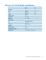
Page 83: ... in Number of colors 262 144 Contrast ratio 200 1 typical Brightness 200 nits typical Pixel resolution Pitch 0 197 mm 0 197 mm Format 1366 768 Configuration RGB vertical stripe Backlight LED Character display 80 25 Total power consumption 2 0 W Viewing angle 65 horizontal 50 vertical typical 39 6 mm 15 6 inch display specifications 75 ...

Page 84: ...fer to HP Support Assistant To access HP Support Assistant on the Start screen select the HP Support Assistant app Backing up your information Recovery after a system failure is as good as your most recent backup You should create system repair media and your initial backup immediately after initial system setup As you add new software and data files you should continue to back up your system on a...

Page 85: ...tion you have previously backed up You can also use Windows Automatic Repair to fix problems that might prevent Windows from starting correctly f11 recovery tools You can use the f11 recovery tools to recover your original hard drive image The image includes the Windows operating system and software programs installed at the factory NOTE If you are unable to boot start up your computer and you can...

Page 86: ...ow the on screen instructions NOTE For additional information on recovering information using the Windows tools perform a search for these topics in HP Support Assistant To access HP Support Assistant on the Start screen select the HP Support Assistant app Using f11 recovery tools CAUTION Using f11 completely erases hard drive contents and reformats the hard drive All files that you have created a...

Page 87: ... and any software that you have installed on the computer are permanently removed When reformatting is complete the recovery process helps you restore the operating system as well as drivers software and utilities To initiate recovery using a Windows 8 operating system DVD NOTE This process takes several minutes 1 If possible back up all personal files 2 Restart the computer and then insert the Wi...

Page 88: ...e screen to display the charms 2 Click Settings 3 Click Change PC settings in the bottom right corner of the screen and then select General from the PC settings screen 4 Under Refresh your PC without affecting your files select Get started and follow the on screen instructions Remove everything and reinstall Windows Sometimes you want to perform detailed reformatting of your computer or you want t...

Page 89: ...ngs screen 4 Under Remove everything and reinstall Windows select Get started and follow the on screen instructions Using HP Software Setup HP Software Setup can be used to reinstall drivers or select software that has been corrupted or deleted from the system 1 From the Start screen type HP Software Setup and select Apps 2 Open HP Software Setup 3 Follow the on screen directions to reinstall driv...

Page 90: ...equirements are applicable to all countries and regions The length of the power cord set must be at least 1 0 m 3 3 ft and no more than 2 0 m 6 5 ft All power cord sets must be approved by an acceptable accredited agency responsible for evaluation in the country or region where the power cord set will be used The power cord sets must have a minimum current capacity of 10 A and a nominal voltage ra...

Page 91: ...ark DEMKO 1 Finland FIMKO 1 France UTE 1 Germany VDE 1 India ISI 1 Israel SII 1 Italy IMQ 1 Japan JIS 3 The Netherlands KEMA 1 New Zealand SANZ 1 Norway NEMKO 1 The People s Republic of China CCC 4 Saudi Arabia SASO 7 Singapore PSB 1 South Africa SABS 1 South Korea KTL 5 Sweden SEMKO 1 Switzerland SEV 1 Taiwan BSMI 6 Thailand TISI 1 The United Kingdom ASTA 1 Requirements for specific countries and...

Page 92: ...0 75 mm or 1 25 mm conductor size The wall plug must be a two pole grounding type with a Japanese Industrial Standard C8303 7 A 125 V ac configuration 4 The flexible cord must be Type RVV 3 conductor 0 75 mm conductor size Power cord set fittings appliance coupler and wall plug must bear the CCC certification mark 5 The flexible cord must be Type H05VV F 3X0 75 mm conductor size KTL logo and indiv...

Page 93: ...e battery in general household waste Follow the local laws and regulations in your area for battery disposal HP encourages customers to recycle used electronic hardware HP original print cartridges and rechargeable batteries For more information about recycling programs see the HP Web site at http www hp com recycle 85 ...

Page 94: ... D display specifications 75 display assembly removal 58 63 spare part numbers 18 24 58 63 spare parts 24 display panel product description 1 drives preventing damage 26 DVD RW and CD RW Super Multi Double Layer Combo Drive precautions 26 E electrostatic discharge 26 equipment guidelines 29 esc key identifying 11 Ethernet product description 2 external media cards product description 3 F f11 recov...

Page 95: ...r connector cable removal 43 spare part number 43 power connector identifying 14 power cord set requirements 82 spare part numbers 22 power light identifying 9 13 power requirements product description 4 processor product description 1 product description audio 2 chipset 1 display panel 1 Ethernet 2 external media cards 3 graphics 1 hard drives 2 internal card expansion 3 keyboard 4 memory module ...

Page 96: ...ad zone identifying 8 transporting guidelines 28 U USB 2 0 port identifying 14 USB 3 0 charging port identifying 12 USB 3 0 port identifying 12 USB audio board removal 42 spare part number 19 23 42 spare parts 24 42 V vents identifying 15 video product description 2 W warranty period 16 webcam identifying 6 webcam assembly spare parts 24 webcam light identifying 6 Windows Refresh 80 reinstall 80 r...

Reviews: