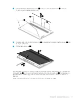
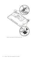
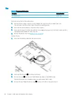
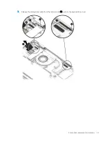
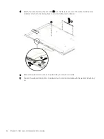
background image

3.

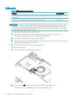
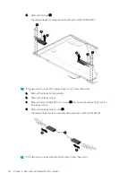
Disconnect the WLAN antenna cables (2) from the WLAN module terminals.

NOTE:

The #1/white WLAN antenna cable connects to the WLAN module #1/Main terminal. The #2/black 

WLAN antenna cable connects to the WLAN module #2/Aux terminal.

4.

Remove the Phillips M2.0×3.0 screw (3) that secures the WLAN module to the system board. 
(The WLAN module tilts up.)
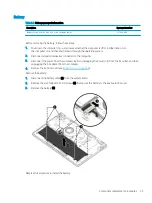
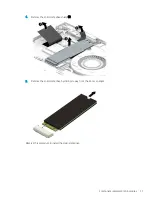
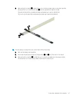
5.

Remove the WLAN module (4) by pulling the module away from the slot at an angle.

NOTE:

WLAN modules are notched to prevent incorrect installation.

Reverse this procedure to install the WLAN module.
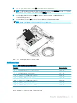
Solid-state drive

Table 5-4

  Solid-state drive spare part information

Description

Spare part number

1 TB, M.2 2280, PCIe, NVMe-3×4, SS solid-state drive with TLC

L85348-005

1 TB, M.2 2280, PCIe, NVMe, value solid-state drive

L85370-005

512 GB, M.2 2280, PCIe-3×4, SS solid-state drive with TLC

L85360-005

512 GB, M.2 2280, PCIe, NVMe, value solid-state drive

L85364-005

256 GB, M.2 2280, PCIe-3×4, SS solid-state drive with TLC

L85350-005

256 GB, M.2 2280, PCIe, NVMe, value solid-state drive

L85354-005

128 GB, M.2 2280, PCIe, NVMe, solid-state drive with TLC

L90345-005

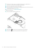
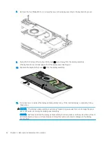
Before removing the solid-state drive, follow these steps:

Component replacement procedures

35

Summary of Contents for ENVY x360 13

Page 1: ...Maintenance and Service Guide HP ENVY x360 13 Convertible PC IMPORTANT This document is intended for HP authorized service providers only ...

Page 2: ...mber L84348 001 Product notice This guide describes features that are common to most models Some features may not be available on your computer Not all features are available in all editions or versions of Windows Systems may require upgraded and or separately purchased hardware drivers software or BIOS update to take full advantage of Windows functionality Windows 10 is automatically updated whic...

Page 3: ...a hard flat surface Do not allow another hard surface such as an adjoining optional printer or a soft surface such as pillows or rugs or clothing to block airflow Also do not allow the AC adapter to contact the skin or a soft surface such as pillows or rugs or clothing during operation The computer and the AC adapter comply with the user accessible surface temperature limits defined by applicable ...

Page 4: ...iv Safety warning notice ...

Page 5: ...om 12 Labels 13 3 Illustrated parts catalog 15 Computer major components 16 Display components 22 Miscellaneous parts 23 4 Removal and replacement procedures preliminary requirements 25 Tools required 25 Service considerations 25 Plastic parts 25 Cables and connectors 25 Drive handling 26 Electrostatic discharge damage 26 Packaging and transporting guidelines 27 Workstation guidelines 28 Equipment...

Page 6: ... Changing the boot order using the f9 prompt 67 TPM BIOS settings select products only 67 Using HP Sure Start select products only 68 7 Backing up restoring and recovering 69 Backing up information and creating recovery media 69 Using Windows tools 69 Using the HP Cloud Recovery Download Tool to create recovery media select products only 69 Restoring and recovery 70 Restoring resetting and refresh...

Page 7: ...wnloading HP PC Hardware Diagnostics UEFI by product name or number select products only 75 Using Remote HP PC Hardware Diagnostics UEFI settings select products only 75 Downloading Remote HP PC Hardware Diagnostics UEFI 75 Downloading the latest Remote HP PC Hardware Diagnostics UEFI version 75 Downloading Remote HP PC Hardware Diagnostics UEFI by product name or number 75 Customizing Remote HP P...

Page 8: ...viii ...

Page 9: ...s 400 nits 13 3 inch LCD FHD 1920 1080 brightView WLED UWVA 72 VAD eDP 1 3 PSR bent direct bonding touchscreen display panel with narrow bezel and generation 3 privacy typical brightness 300 nits Memory Support for DDR4 3200 1 2 V nonupgradeable onboard system memory in 16 GB and 8 GB configurations Storage Support for the following solid state drives 1 TB 2280 peripheral component interconnect ex...

Page 10: ...clickpad with image sensor Island style backlit standard notebook privacy keyboard in ceramic white finish with clickpad with image sensor Island style backlit standard notebook keyboard in nightfall black finish with clickpad with image sensor Island style backlit standard notebook privacy keyboard in nightfall black finish with clickpad with image sensor Touchpad requirements Clickpad with image...

Page 11: ...ndows 10 Home 64 bit Plus Single Language Africa Market PPP Windows 10 Home 64 bit Plus Single Language Asia Pacific Emerging Market PPP Windows 10 Home 64 bit Plus Single Language India Market PPP Windows 10 Home 64 bit Plus Single Language Indonesia Market PPP Windows 10 Professional 64 bit Serviceability End user replaceable parts AC adapter 3 ...

Page 12: ... manager in the taskbar search box and then select the Device Manager app A list displays all the devices installed on the computer For information about system hardware components and the system BIOS version number press fn esc select products only Locating software Software varies by product To find out what software is installed on the computer Right click the Start button and then select Apps ...

Page 13: ...d then remove it from the memory card reader 2 USB SuperSpeed port with HP Sleep and Charge Connects a USB device provides high speed data transfer and even when the computer is off charges most products such as a cell phone camera activity tracker or smartwatch 3 AC adapter and battery light White The AC adapter is connected and the battery is fully charged Blinking white select products only The...

Page 14: ...box and then select HP Documentation NOTE When a device is connected to the jack the computer speakers are disabled 2 USB SuperSpeed port Connects a USB device such as a cell phone camera activity tracker or smartwatch and provides high speed data transfer 3 USB Type C port with HP Sleep and Charge Connects an AC adapter that has a USB Type C connector supplying power to the computer and if needed...

Page 15: ...r descriptions Component Description 1 WLAN antenna s 2 Send and receive wireless signals to communicate with WLANs 2 Internal microphones Record sound 3 Camera Allows you to video chat record video and record still images Some cameras also allow a facial recognition logon to Windows instead of a password logon NOTE Camera functions vary depending on the camera hardware and software installed on t...

Page 16: ... enter 2 Using an external mouse click the touchpad button or Press the Tab key repeatedly until the pointer rests on the touchpad button Then press the spacebar to select the button Table 2 4 Touchpad components and their descriptions Component Description 1 Touchpad zone Reads finger gestures to move the pointer or activate items on the screen 2 Left touchpad button Functions like the left butto...

Page 17: ...ne is off Off Microphone is on 4 Camera privacy light On The camera is off Off The camera is on 5 Power light On The computer is on Blinking select products only The computer is in the Sleep state a power saving state The computer shuts off power to the display and other unnecessary components Off Depending on the computer model the computer is off in Hibernation or in Sleep Hibernation is the pow...

Page 18: ...eader 2 Power button When the computer is off press the button to turn on the computer When the computer is on press the button briefly to initiate Sleep When the computer is in the Sleep state press the button briefly to exit Sleep select products only When the computer is in Hibernation press the button briefly to exit Hibernation IMPORTANT Pressing and holding down the power button results in t...

Page 19: ...rint logon to Windows instead of a password logon Touch a finger to the fingerprint reader IMPORTANT To prevent fingerprint logon issues make sure when registering a fingerprint that all sides of the finger are registered by the fingerprint reader 6 Camera privacy switch Turns the camera off and on 7 Power button When the computer is off press the button to turn on the computer When the computer i...

Page 20: ...or at least 10 seconds to turn off the computer Bottom Table 2 8 Bottom components and their descriptions Component Description 1 Vent Enables airflow to cool internal components NOTE The computer fan starts up automatically to cool internal components and prevent overheating It is normal for the internal fan to cycle on and off during routine operation 2 Speakers 2 Produce sound 12 Chapter 2 Comp...

Page 21: ...e bottom of a tablet kickstand Service label Provides important information to identify the computer When contacting support the serial number the product number or the model number might be requested Locate this information before contacting support The service label will resemble one of the following examples Refer to the illustration that most closely matches the service label on the computer T...

Page 22: ...riod Regulatory label s Provide s regulatory information about the computer Wireless certification label s Provide s information about optional wireless devices and the approval markings for the countries or regions in which the devices have been approved for use 14 Chapter 2 Components ...

Page 23: ...TE HP continually improves and changes product parts For complete and current information about supported parts for the computer go to http partsurfer hp com select the country or region and then follow the on screen instructions 15 ...

Page 24: ...ssembly is available as spare parts at the subcomponent level only For more display assembly spare part information see Display components on page 22 2 Keyboard top cover with backlight and touchpad in nightfall black finish keyboard and wood finish top cover includes backlight cable and keyboard cable 16 Chapter 3 Illustrated parts catalog ...

Page 25: ... L94516 131 For use in Russia L94516 251 For use in Saudi Arabia L94516 171 For use in South Korea L94516 AD1 For use in Spain L94516 071 For use in Switzerland L94516 BG1 For use in Taiwan L94516 AB1 For use in Thailand L94516 281 For use in Turkey L94516 141 For use in the Ukraine L94516 BD1 For use in the United Kingdom L94516 031 For use in the United States L94516 001 Keyboard top cover with ...

Page 26: ... use in Thailand L94515 281 For use in Turkey L94515 141 For use in the Ukraine L94515 BD1 For use in the United Kingdom L94515 031 For use in the United States L94515 001 Keyboard top cover with backlight in nightfall black finish includes backlight cable and keyboard cable For use only on computer models equipped with a display assembly with privacy filter For use in Belgium L94517 A41 For use i...

Page 27: ...cover with backlight in nightfall black finish includes backlight cable and keyboard cable For use only on computer models not equipped with a display assembly with privacy filter For use in Belgium L94518 A41 For use in Canada L94518 DB1 For use in the Czech Republic and Slovakia L94518 FL1 For use in Denmark Finland and Norway L94518 DH1 For use in France L94518 051 For use in Germany L94518 041...

Page 28: ...4 SS solid state drive with TLC L85350 005 256 GB M 2 2280 PCIe NVMe value solid state drive L85354 005 128 GB M 2 2280 PCIe NVMe solid state drive with TLC L90345 005 7b Solid state drive shield not available as a spare part 8 WLAN module Intel Wi Fi 6 AX200 ax 2 2 Bluetooth 5 0 MU MIMO M 2 2230 non vPro 160 MHz PCI e USB worldwide with 2 antenna s L35282 005 Realtek ac 2 2 Bluetooth 5 0 M 2 2230...

Page 29: ...9 601 12 Heat sink includes replacement thermal material L94510 001 13 Fan includes cable L94511 001 14 Infrared board L94506 001 Infrared board cable not illustrated L94507 001 15 Bottom cover L94514 001 Bottom cover adhesive tape not illustrated M11730 001 USB port cover not illustrated L95695 001 Rubber feet not illustrated L94496 001 Computer major components 21 ...

Page 30: ...y filter L94502 001 For use only on computer models not equipped with a display panel assembly with a privacy filter L94501 001 3 Touch control board cable includes webcam microphone module cable and double sided adhesive L94500 001 4 Webcam microphone module includes double sided adhesive L94505 001 5 Touch control board includes double sided adhesive L94497 001 6 Wireless Antenna Kit includes an...

Page 31: ... 001 HP USB C to RJ45 adapter 855560 001 HP USB C to USB A dongle 833960 001 HP USB C to USB A hub 916838 001 HP USB C to VGA adapter 831751 001 HP USB external DVD RW Drive 747080 001 Pen Zenvo pen with cable In natural silver finish L95614 001 In nightfall black finish L95615 001 Pen tip Sunwoda Cadillac L04536 001 Power cord C5 1 0 m premium with sticker For use in Argentina L30811 001 For use ...

Page 32: ... in Switzerland L22324 001 For use in Taiwan L22329 001 For use in Thailand L22326 001 For use in the United Kingdom L22320 001 Screw Kit L95411 001 Stylus Sunwoda stylus active pen In dark ash silver finish 920241 001 In natural silver finish 910942 001 24 Chapter 3 Illustrated parts catalog ...

Page 33: ...astic parts IMPORTANT Using excessive force during disassembly and reassembly can damage plastic parts Use care when handling the plastic Cables and connectors IMPORTANT When servicing the computer be sure that cables are placed in their proper locations during the reassembly process Improper cable placement can damage the computer Cables must be handled with extreme care to avoid damage Apply onl...

Page 34: ...ve to electrostatic discharge ESD Circuitry design and structure determine the degree of sensitivity Networks built into many integrated circuits provide some protection but in many cases ESD contains enough power to alter device parameters or melt silicon junctions A discharge of static electricity from a finger or other conductor can destroy static sensitive devices or microcircuitry Even if the...

Page 35: ...ipment To avoid hand contact transport products in static safe tubes bags or boxes Protect ESD sensitive parts and assemblies with conductive or approved containers or packaging Keep ESD sensitive parts in their containers until the parts arrive at static free workstations Place items on a grounded surface before removing items from their containers Always be properly grounded when touching a comp...

Page 36: ...minimum of 1 MΩ 10 resistance in the ground cords To provide proper ground wear a strap snugly against the skin at all times On grounded mats with banana plug connectors use alligator clips to connect a wrist strap When standing use foot straps and a grounded floor mat Foot straps heel toe or boot straps can be used at standing workstations and are compatible with most types of shoes or boots On c...

Page 37: ...tic bags and floor mats Table 4 2 Shielding protection provided by antistatic bags and floor mats Material Use Voltage protection level Antistatic plastics Bags 1 500 V Carbon loaded plastic Floor mats 7 500 V Metallized laminate Floor mats 5 000 V Equipment guidelines 29 ...

Page 38: ...special note of each screw size and location during removal and replacement Bottom cover Table 5 1 Bottom cover spare part information Description Spare part number Bottom cover L94514 001 Remove the bottom cover 1 Shut down the computer If you are unsure whether the computer is off or in Hibernation turn the computer on and then shut it down through the operating system 2 Disconnect all external ...

Page 39: ...over 8 Remove the bottom cover 3 Each time the bottom cover is removed and replaced inspect the adhesive tape located on the AC adapter and battery light pipe 1 and the audio out headphone audio in microphone combo jack 2 This tape ensures that the bottom cover fits snugly at these contact points Replacement adhesive tape should be 0 3 mm in thickness The bottom cover adhesive tape is available us...

Page 40: ...Reverse this procedure to install the bottom cover 32 Chapter 5 Removal and replacement procedures ...

Page 41: ...g system 2 Disconnect all external devices connected to the computer 3 Disconnect the power from the computer by first unplugging the power cord from the AC outlet and then unplugging the AC adapter from the computer 4 Remove the bottom cover see Bottom cover on page 30 Remove the battery 1 Disconnect the battery cable 1 from the system board 2 Remove the six Phillips M2 0 4 0 screws 2 that secure...

Page 42: ...re device functionality and then contact technical support Before removing the WLAN module follow these steps 1 Shut down the computer If you are unsure whether the computer is off or in Hibernation turn the computer on and then shut it down through the operating system 2 Disconnect all external devices connected to the computer 3 Disconnect the power from the computer by first unplugging the powe...

Page 43: ...verse this procedure to install the WLAN module Solid state drive Table 5 4 Solid state drive spare part information Description Spare part number 1 TB M 2 2280 PCIe NVMe 3 4 SS solid state drive with TLC L85348 005 1 TB M 2 2280 PCIe NVMe value solid state drive L85370 005 512 GB M 2 2280 PCIe 3 4 SS solid state drive with TLC L85360 005 512 GB M 2 2280 PCIe NVMe value solid state drive L85364 00...

Page 44: ...ter by first unplugging the power cord from the AC outlet and then unplugging the AC adapter from the computer 4 Remove the bottom cover see Bottom cover on page 30 Remove the solid state drive 1 Disconnect the battery cable from the system board 2 Release the cover 1 that secures the solid state drive shield to the system board 3 Remove the tape 2 that secures the solid state drive to the keyboar...

Page 45: ...emove the solid state drive shield 3 5 Remove the solid state drive by sliding it away from the slot at an angle Reverse this procedure to install the solid state drive Component replacement procedures 37 ...

Page 46: ... power from the computer by first unplugging the power cord from the AC outlet and then unplugging the AC adapter from the computer 4 Remove the bottom cover see Bottom cover on page 30 Remove the fan 1 Disconnect the battery cable from the system board 2 Disconnect the fan cable 1 from the system board 3 Remove the cover 2 that secures the WLAN antenna cables to the WLAN module The WLAN module co...

Page 47: ...5 Remove the fan 4 Reverse this procedure to install the fan Component replacement procedures 39 ...

Page 48: ...from the system board 2 Release the zero insertion force ZIF connector 1 to which the webcam microphone module cable is connected and then disconnect the webcam microphone module cable from the system board 3 Remove the cover 2 that secures the WLAN antenna cables to the WLAN module The WLAN module cover is available using spare part number L98315 005 4 Disconnect the WLAN antenna cables 3 from th...

Page 49: ...7 Release the display panel cable from the retention clip 6 built into the keyboard top cover Component replacement procedures 41 ...

Page 50: ...is necessary to replace the display panel assembly or any of the internal display components follow these steps CAUTION The display panel assembly is extremely fragile Using excessive force can damage the panel Use caution when removing the display panel assembly CAUTION Before positioning the display panel assembly face down make sure the work surface is free of all foreign objects screws and too...

Page 51: ...cing up and the bottom edge of the assembly toward you e Use a case utility tool 1 or similar thin plastic tool to separate the top edge of the display panel assembly from the display back cover NOTE Slow steady pressure is required when working with the pull to release tabs in substep f Pulling too fast can result in the tabs breaking and the release action being incomplete f Grasp the pull to re...

Page 52: ...les from the display right hinge 2 j Remove the display panel assembly 3 The display panel assembly is available using the following spare part numbers L94495 001 13 3 in FHD 1000 nit touchscreen display panel assembly with privacy filter L94494 001 13 3 in FHD 400 nit touchscreen display panel assembly L94493 001 13 3 in FHD 300 nit touchscreen display panel assembly 44 Chapter 5 Removal and repl...

Page 53: ...ve the display panel assembly b Disconnect the touch control board cables from the touch control board two locations 1 c Detach the touch control board cable 2 from the display back cover The touch control board cable is attached to the display back cover with double sided adhesive Component replacement procedures 45 ...

Page 54: ...e module is attached to the display back cover with double sided adhesive e Remove the webcam microphone module and touch control board cable f Position the webcam microphone module and touch control board cable with the webcam lens facing up 46 Chapter 5 Removal and replacement procedures ...

Page 55: ...ntrol board cable is available using spare part number L94500 001 13 If it is necessary to replace the touch control board follow these steps a Remove the display panel assembly b Disconnect the webcam microphone module cables 1 and 2 from the touch control board c Release the ZIF connectors 3 to which the touch control board cables are connected and then disconnect the touch control board cables ...

Page 56: ... is available using spare part number L94497 001 14 If it is necessary to replace the display panel cable follow these steps a Remove the display panel assembly b Release the grounding strip 1 that secures the display panel cable to the display panel c Release the adhesive support strip 2 that secures the display panel cable to the display panel 48 Chapter 5 Removal and replacement procedures ...

Page 57: ...y filter and L94501 001 for use only on computer models not equipped with a display panel assembly with a privacy filter 15 If it is necessary to replace the display hinges follow these steps a Remove the display panel assembly b Remove the four Phillips M2 5 3 5 screws 1 that secure the display hinges to the display back cover c Release the grouding tape 2 that secures the display hinges to the d...

Page 58: ...display panel assembly b Remove the display hinges c Remove the two Phillips M2 0 4 1 screws 1 that secure the display hinge covers to the display hinges d Remove the display hinge covers 2 The display hinge covers are available using spare part number L94504 001 17 If it is necessary to replace the WLAN antenna s follow these steps 50 Chapter 5 Removal and replacement procedures ...

Page 59: ...attached to the display back cover with double sided tape d Release the antenna cables from the routing channels 2 built into the display back cover e Remove the WLAN antenna cables and transceivers 3 The WLAN antenna s are available using spare part number L94503 001 Reverse this procedure to reassemble and install the display assembly Component replacement procedures 51 ...

Page 60: ...2 Disconnect all external devices connected to the computer 3 Disconnect the power from the computer by first unplugging the power cord from the AC outlet and then unplugging the AC adapter from the computer 4 Remove the bottom cover see Bottom cover on page 30 5 Remove the display assembly see Display assembly on page 40 Remove the power connector cable 1 Disconnect the power connector cable 1 fr...

Page 61: ...external devices connected to the computer 3 Disconnect the power from the computer by first unplugging the power cord from the AC outlet and then unplugging the AC adapter from the computer 4 Remove the bottom cover see Bottom cover on page 30 5 Remove the battery see Battery on page 33 Remove the speakers 1 Disconnect the speaker cable 1 from the system board 2 Release the tape tabs 2 that secur...

Page 62: ... speakers make note of the location of the four rubber isolators 5 The absence of or damage to these isolators can result in degraded speaker performance Reverse this procedure to install the speakers 54 Chapter 5 Removal and replacement procedures ...

Page 63: ...nd then unplugging the AC adapter from the computer 4 Remove the bottom cover see Bottom cover on page 30 5 Remove the battery see Battery on page 33 Remove the touchpad cable 1 Detach the touchpad cable 1 from the keyboard top cover The touchpad cable is attached to the keyboard top cover with double sided tape 2 Release the ZIF connector 2 to which the touchpad cable is connected and then discon...

Page 64: ...ttom cover see Bottom cover on page 30 5 Remove the battery see Battery on page 33 Remove the touchpad 1 Detach the touchpad cable 1 from the keyboard top cover The touchpad cable is attached to the keyboard top cover with double sided tape 2 Release the ZIF connector 2 to which the touchpad cable is connected and then disconnect the touchpad cable from the system board 3 Remove the three Phillips...

Page 65: ...6 Remove the touchpad 6 and cable Reverse this procedure to install the touchpad Component replacement procedures 57 ...

Page 66: ...bernation turn the computer on and then shut it down through the operating system 2 Disconnect all external devices connected to the computer 3 Disconnect the power from the computer by first unplugging the power cord from the AC outlet and then unplugging the AC adapter from the computer 4 Remove the bottom cover see Bottom cover on page 30 and then remove the following components a Battery see B...

Page 67: ...ack WLAN antenna cable connects to the WLAN module 2 Aux terminal 5 Infrared board ZIF connector cable 6 Display panel ZIF connector cable 7 Backlight ZIF connector cable 8 Keyboard ZIF connector cable 9 Fingerprint reader ZIF connector cable 10 Touchpad ZIF connector cable 11 Speaker cable 3 Remove the three Phillips M2 0 2 3 broad head screws 1 that secure the system board to the keyboard top co...

Page 68: ...I O bracket 3 to the keyboard top cover 5 Lift the left side the system board 1 until it rests at an angle 6 Remove the system board 2 by sliding it up and to the right at an angle Reverse this procedure to install the system board 60 Chapter 5 Removal and replacement procedures ...

Page 69: ...t and then unplugging the AC adapter from the computer 4 Remove the bottom cover see Bottom cover on page 30 and then remove the following components a Battery see Battery on page 33 b Solid state drive see Solid state drive on page 35 c Fan see Fan on page 38 d System board see System board on page 58 Remove the heat sink 1 Remove the four Phillips M2 0 4 0 screws 1 that secure the heat sink to t...

Page 70: ...Reverse this procedure to install the heat sink 62 Chapter 5 Removal and replacement procedures ...

Page 71: ...y first unplugging the power cord from the AC outlet and then unplugging the AC adapter from the computer 4 Remove the bottom cover see Bottom cover on page 30 and then remove the following components a Battery see Battery on page 33 b Solid state drive see Solid state drive on page 35 c Fan see Fan on page 38 d System board see System board on page 58 Remove the infrared board cable 1 Release the...

Page 72: ...ter by first unplugging the power cord from the AC outlet and then unplugging the AC adapter from the computer 4 Remove the bottom cover see Bottom cover on page 30 and then remove the following components a Battery see Battery on page 33 b Solid state drive see Solid state drive on page 35 c Fan see Fan on page 38 d System board see System board on page 58 Remove the infrared board 1 Remove the P...

Page 73: ...ow key or the down arrow key on the keyboard To close open dialog boxes and return to the main Computer Setup screen press esc and then follow the on screen instructions To exit Computer Setup choose one of the following methods To exit Computer Setup menus without saving your changes select Main select Ignore Changes and Exit and then select Yes NOTE If you are using arrow keys to highlight your ...

Page 74: ...r changes select Main select Ignore Changes and Exit and then select Yes NOTE If you are using arrow keys to highlight your choice you must then press enter To check for later BIOS versions see Downloading a BIOS update on page 66 Downloading a BIOS update IMPORTANT To reduce the risk of damage to the computer or an unsuccessful installation download and install a BIOS update only when the compute...

Page 75: ... screen instructions NOTE After a message on the screen reports a successful installation you can delete the downloaded file from your hard drive Changing the boot order using the f9 prompt To dynamically choose a boot device for the current startup sequence follow these steps 1 Access the Boot Device Options menu Turn on or restart the computer and when the HP logo appears press f9 to enter the B...

Page 76: ...estores the BIOS to its previously safe state without user intervention HP Sure Start is configured and already enabled so that most users can use the HP Sure Start default configuration Advanced users can customize the default configuration To access the latest documentation on HP Sure Start go to http www hp com support Select Find your product and then follow the on screen instructions 68 Chapt...

Page 77: ...covery process IMPORTANT For a tablet with a detachable keyboard connect the tablet to the keyboard base before beginning any recovery process Backing up information and creating recovery media Using Windows tools IMPORTANT Windows is the only option that allows you to back up your personal information Schedule regular backups to avoid information loss You can use Windows tools to back up personal...

Page 78: ...instructions To recover your system Insert the HP Recovery media and then restart the computer Changing the computer boot order If your computer does not restart using the HP Recovery media you can change the computer boot order This is the order of devices listed in BIOS where the computer looks for startup information You can change the selection to an optical drive or a USB flash drive dependin...

Page 79: ...thout installed recovery software Using HP Sure Recover an administrator or user can restore the system and install Latest version of the operating system Platform specific device drivers Software applications in the case of a custom image To access the latest documentation for HP Sure Recover go to http www hp com support Select Find your product and then follow the on screen instructions Restori...

Page 80: ...cess HP PC Hardware Diagnostics Windows from HP Support Assistant a Type support in the taskbar search box and then select the HP Support Assistant app or Select the question mark icon in the taskbar b Select Troubleshooting and fixes c Select Diagnostics and then select HP PC Hardware Diagnostics Windows 2 When the tool opens select the type of diagnostic test that you want to run and then follow...

Page 81: ...me or number in the search box that is displayed 3 In the Diagnostics section select Download and then follow the on screen instructions to select the specific Windows diagnostics version to be downloaded to your computer or USB flash drive The tool downloads to the selected location Installing HP PC Hardware Diagnostics Windows To install HP PC Hardware Diagnostics Windows follow these steps Navi...

Page 82: ...are Diagnostics UEFI tool to a USB flash drive see Downloading the latest HP PC Hardware Diagnostics UEFI version on page 74 b Hard drive c BIOS 3 When the diagnostic tool opens select a language select the type of diagnostic test you want to run and then follow the on screen instructions Downloading HP PC Hardware Diagnostics UEFI to a USB flash drive Downloading HP PC Hardware Diagnostics UEFI t...

Page 83: ... NOTE HP Remote PC Hardware Diagnostics UEFI is also available as a SoftPaq that you can download to a server Downloading the latest Remote HP PC Hardware Diagnostics UEFI version To download the latest Remote HP PC Hardware Diagnostics UEFI version follow these steps 1 Go to http www hp com go techcenter pcdiags The HP PC Diagnostics home page is displayed 2 Select Download Remote Diagnostics and...

Page 84: ...h drive to run remote diagnostics Set a location for storing the test results You can also set the user name and password that you use for uploads Display status information about the diagnostics run previously To customize Remote HP PC Hardware Diagnostics UEFI settings follow these steps 1 Turn on or restart the computer and when the HP logo appears press f10 to enter Computer Setup 2 Select Adv...

Page 85: ... regulatory label Table 9 1 Computer specifications Metric U S Dimensions Width 30 7 cm 12 1 in Depth 19 5 cm 7 7 in Height 1 6 cm 0 7 in Weight 1 3 kg 2 9 lbs Input power Rating Operating voltage and current 5 V dc 2 A 12 V dc 3 A 15 V dc 3 A 45 W USB C 5 V dc 3 A 9 V dc 3 A 12 V dc 3 75 A 15 V dc 3 A 45 W USB C 5 V dc 3 A 9 V dc 3 A 10 V dc 3 75 A 12 V dc 3 75 A 15 V dc 3 A 20 V dc 2 25 A 45 W U...

Page 86: ...dity noncondensing Operating 10 to 90 Nonoperating 5 to 95 Maximum altitude unpressurized Operating 15 m to 3 048 m 50 ft to 10 000 ft Nonoperating 15 m to 12 192 m 50 ft to 40 000 ft NOTE Applicable product safety standards specify thermal limits for plastic surfaces The device operates well within this range of temperatures 78 Chapter 9 Specifications ...

Page 87: ...equirements are applicable to all countries and regions The length of the power cord set must be at least 1 0 m 3 3 ft and no more than 2 0 m 6 5 ft All power cord sets must be approved by an acceptable accredited agency responsible for evaluation in the country or region where the power cord set will be used The power cord sets must have a minimum current capacity of 10 A and a nominal voltage ra...

Page 88: ...JIS 3 The Netherlands KEMA 1 New Zealand SANZ 1 Norway NEMKO 1 The People s Republic of China CCC 4 Saudi Arabia SASO 7 Singapore PSB 1 South Africa SABS 1 South Korea KTL 5 Sweden SEMKO 1 Switzerland SEV 1 Taiwan BSMI 6 Thailand TISI 1 The United Kingdom ASTA 1 The United States UL 2 1 The flexible cord must be Type HO5VV F 3 conductor 0 75 mm conductor size Power cord set fittings appliance coup...

Page 89: ...303 7 A 125 V ac configuration 4 The flexible cord must be Type RVV 3 conductor 0 75 mm conductor size Power cord set fittings appliance coupler and wall plug must bear the CCC certification mark 5 The flexible cord must be Type H05VV F 3 conductor 0 75 mm conductor size KTL logo and individual approval number must be on each element Approval number and logo must be printed on a flag label 6 The f...

Page 90: ...in general household waste Follow the local laws and regulations in your area for battery disposal HP encourages customers to recycle used electronic hardware HP original print cartridges and rechargeable batteries For more information about recycling programs see the HP Web site at http www hp com recycle 82 Chapter 11 Recycling ...

Page 91: ...s 16 Computer Setup navigating and selecting 65 restoring factory settings 65 starting 65 computer setup 65 computer specifications 77 connectors power 5 D display assembly removal 40 spare part numbers 40 display back cover spare part number 22 display components 7 22 display panel assembly removal 42 spare part numbers 22 44 display panel cable removal 48 spare part numbers 22 49 display panel p...

Page 92: ...part numbers 23 power light 9 power requirements product description 2 processor product description 1 product description audio 1 chipset 1 display panel 1 expansion 2 graphics 1 media card reader 2 memory 1 microphone 1 operating system 2 3 ports 2 power requirements 2 processors 1 product name 1 security 2 sensors 2 serviceability 3 storage 1 video 1 wireless 2 product name 1 product name and n...

Page 93: ... cover spare part number 21 USB SuperSpeed port 6 USB SuperSpeed port with HP Sleep and Charge 5 USB Type C port with HP Sleep and Charge 6 V vents 12 video product description 1 W webcam microphone module removal 45 spare part number 22 47 Windows backup 69 recovery media 69 system restore point 69 Windows key 11 Windows tools using 69 Wireless Antenna Kit spare part number 22 wireless antenna s ...

Reviews: