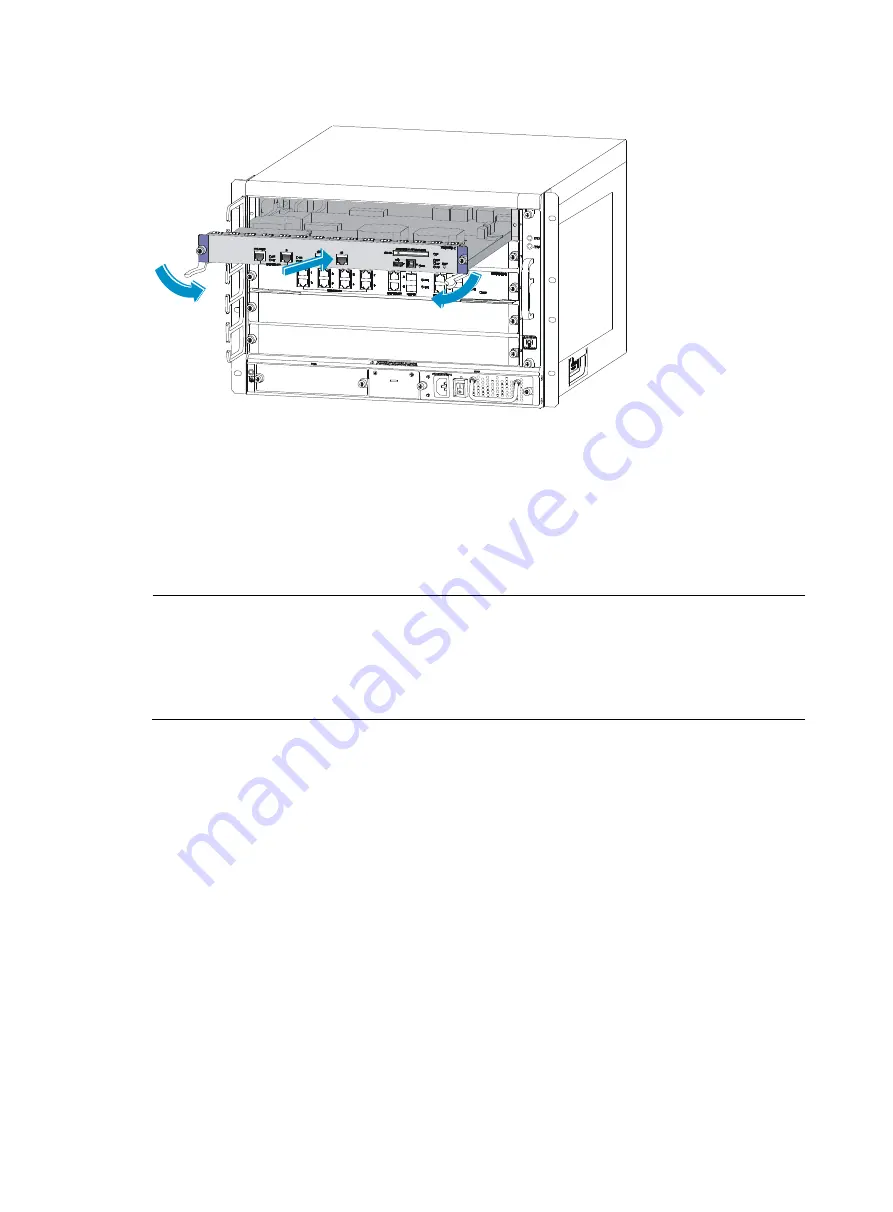
20
Figure 19
Insert the MPU into slot
2.
Fasten the captive screws on the MPU with a Phillips screwdriver.
3.
After the firewall is powered on, the RUN LED flashes fast (at 8 Hz). It flashes slowly (at 1 Hz) after
the application is loaded. This means that the MPU runs properly. For the LED description, see the
chapter “
.”
Installing an interface module
NOTE:
•
An interface module can only be installed in slot 1, 2, 3, or 4.
•
You must install an MPU and at least one interface module for the firewall to operate properly.
•
Typically the firewall does not provide a filler panel for one of the interface module slots when it is
shipped.
The procedures for installing interface modules are the same. The following uses an NSQ1GT8C40 as
an example.
Follow these steps to install an interface module:
1.
Remove the filler panel (if any) from the slot you want to install an interface module: use a Phillips
screwdriver to loosen the captive screws on the filler panel until all spring pressure is released, and
then remove the filler panel.
2.
Push the interface module along the guide rails into the slot until it touches the slot bottom, and then
push the ejector levers inward to lock the interface module in position.
Summary of Contents for F5000
Page 6: ...iv Index 92 ...
Page 11: ...5 Fan trays Figure 9 Fan tray 1 Handle 2 Fans ...


