21
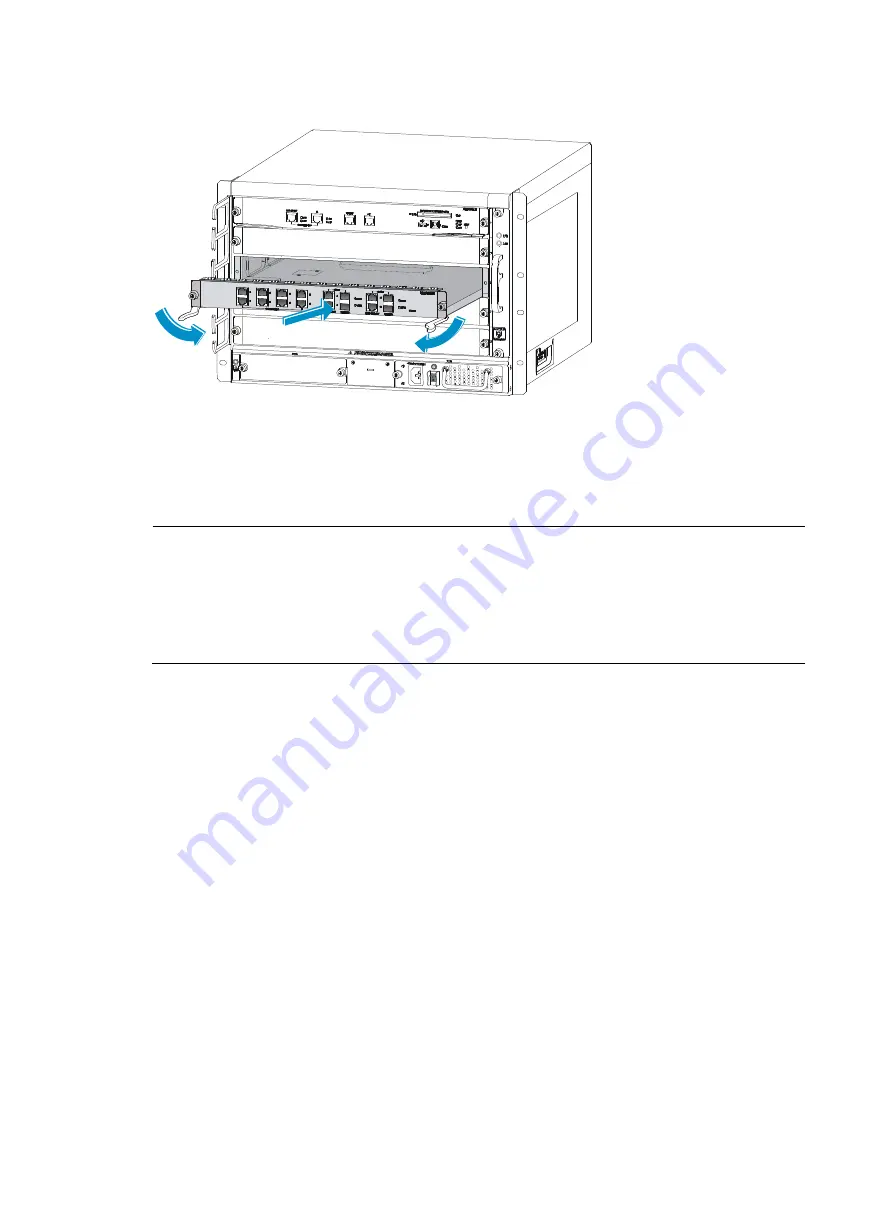
Figure 20
Insert an interface module
3.
Fasten the captive screws on the interface module with a Phillips screwdriver.
4.
After the firewall is powered on, the RUN LED flashes once and then flashes fast (at 8 Hz). It flashes
slowly (at 1 Hz) after the application is loaded. This means that the interface module runs properly.
For more information of the interface module LEDs, see the chapter “
NOTE:
•
If there is a great resistance when you push an interface module into a slot, first remove the filler panels
above and below the slot, then install the interface module. Install the removed filler panels to prevent
dust from entering the chassis.
•
If slots 1 through 4 of the F5000 are all installed with interface modules, the interface modules are
powered on in the sequence of slot 1, slot 2, slot 3, and slot 4, with RUN LEDs lighting up in turn.
Installing a fan tray
Follow these steps to install a fan tray:
1.
Gently push the fan tray slowly along the slide rails into the slot until it touches the slot bottom.
Summary of Contents for F5000
Page 6: ...iv Index 92 ...
Page 11: ...5 Fan trays Figure 9 Fan tray 1 Handle 2 Fans ...


