background image


5.


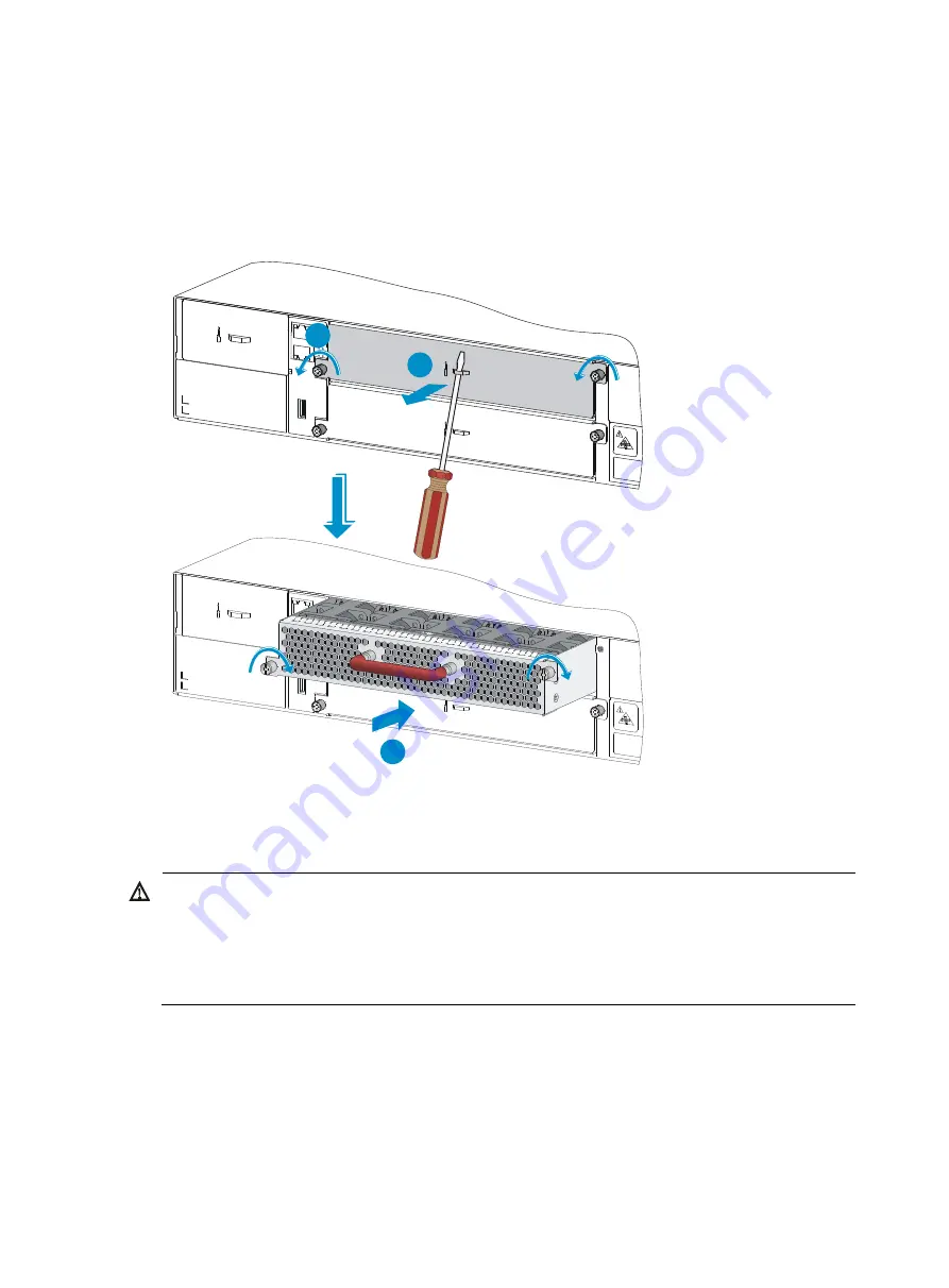
Holding the fan tray with both hands with the upside (marked with a "TOP" sign) up, gently push 

the fan tray into the slot along the guide rails until the fan tray completely seats into the slot. See 
callout 3 in 

Figure 13

6.


Use a Phillips screwdriver to tighten the captive screws on the fan tray to make sure the fan tray is 
fully seated in the slot. 

Figure 13


Installing a fan tray 

1

2

3


Removing a fan tray 


WARNING! 


The new fan tray and the removed fan tray must be the same model. 


Take out the fan tray after the fans completely stop rotating. 


To prevent an unbalanced fan from causing loud noise, do not touch the fans, even if they are not 
rotating. 


To remove a fan tray: 

1.


Wear an ESD wrist strap and make sure it makes good skin contact and is correctly grounded. 

2.


Loosen the captive screw of the fan tray with a Phillips screwdriver until it is fully disengaged from 
the switch chassis. 

13 

Summary of Contents for FlexFabric 7900 Series

Page 1: ...HP FlexFabric 7900 Switch Series Installation Guide Part number 5998 4299 Document version 5W100 20131203 ...

Page 2: ...MATERIAL INCLUDING BUT NOT LIMITED TO THE IMPLIED WARRANTIES OF MERCHANTABILITY AND FITNESS FOR A PARTICULAR PURPOSE Hewlett Packard shall not be liable for errors contained herein or for incidental or consequential damages in connection with the furnishing performance or use of this material The only warranties for HP products and services are set forth in the express warranty statements accompan...

Page 3: ...Installing removing a power supply 14 Installing a power supply 14 Removing a power supply 16 Connecting the power cord 16 Connecting an AC power cord to the switch 16 Installing removing an LPU 17 Installing an LPU 17 Removing an LPU 18 U Verifying the installation 18 Accessing the switch for the first time 20 Setting up the configuration environment 20 Connecting the console cable 20 Setting ter...

Page 4: ...ce 37 Related information 37 Documents 37 Websites 37 Conventions 38 Appendix A Chassis views and technical specifications 40 Chassis views 40 Hardware specifications 41 Weight 41 Chassis dimensions and rack clearance requirements 42 Ports and slots 42 Module power consumption and system power consumption 43 Heat dissipation 43 Environmental specifications 44 Noise 44 Other specifications 44 Cooli...

Page 5: ...iii Index 53 ...

Page 6: ...ch near water or in a damp environment Prevent water or moisture from entering the switch Do not place the switch on an unstable case or desk The switch might be severely damaged in case of a fall Ensure good ventilation of the equipment room and keep the air inlet and outlet vents of the switch free of obstruction Make sure the input voltage is in the required range To avoid electrical shocks do ...

Page 7: ...oose captive screws and circuit failure High temperature can accelerate aging of insulation materials and significantly lower the reliability and lifespan of the switch Cleanness Dust buildup on the chassis might result in electrostatic adsorption which causes poor contact of metal components and contact points especially when indoor relative humidity is low In the worst case electrostatic adsorpt...

Page 8: ...quency devices to make sure the EMI levels do not exceed the compliant range Use electromagnetic shielding for example shielded interface cables when necessary To prevent signal ports from getting damaged by over voltage or over current caused by lightning strikes only route interface cables indoors Laser safety Do not stare into any fiber cables or ports when they are powered on They emit invisib...

Page 9: ...ontact HP for permission Otherwise HP shall not be liable for any consequence Figure 1 Hardware installation flow Installing the switch in a 19 inch rack Mounting bracket and cable management bracket kit The HP 7904 switch comes with a pair of mounting brackets and a cable management bracket attached together You can detach them as required 4 ...

Page 10: ...904 switch also comes with a pair of chassis rails and a pair of slide rails Figure 3 Rack mounting rail kit 1 Chassis rail 2 Slide rail Rack mounting procedures at a glance You can install the HP 7904 switch in a 19 inch rack using the mounting bracket and rack mounting rail kit as described in Figure 4 Figure 4 Rack mounting procedure 5 ...

Page 11: ...kets and grounding cable before installation Figure 5 Installation positions for the mounting brackets and grounding cable 1 Rear mounting position power supply side 2 Primary grounding point 3 Auxiliary grounding point 4 Front mounting position network port side Attaching the mounting brackets and chassis rails to the chassis 1 Align the screw holes in the mounting brackets with the screw holes i...

Page 12: ...ng cable to a chassis grounding point for example the primary grounding point 1 Unpack the grounding cable and grounding screws 2 Align the two hole grounding lug at one end of the cable with the grounding holes of the grounding point insert the grounding screws into the holes and tighten the screws with a screwdriver to attach the grounding lug to the chassis as shown in Figure 6 Figure 6 Attachi...

Page 13: ...er supplied in the mounting holes in the rack posts 3 Align the screw holes in one slide rail with the cage nuts in the rack post on one side and use screws user supplied to attach the slide rail to the rack as shown in Figure 8 4 Repeat the preceding steps to attach the other slide rail to the rack post on the other side Keep the two slide rails at the same height so the slide rails can attach in...

Page 14: ...ser supplied to the front rack posts and make sure they are at the same level as the slide rails 5 Supporting the bottom of the switch align the chassis rails with the slide rails on the rack posts as shown in Figure 9 Work with another person to slide the chassis rails along the slide rails until the mounting brackets are flush with the rack posts 6 Use screws user supplied to attach the mounting...

Page 15: ...y of the switch You can ground the switch by using a grounding strip at the installation site or the AC power cord connected to the switch NOTE The power and grounding terminals in this section are for illustration only Grounding the switch with a grounding strip WARNING Connect the grounding cable to the grounding system in the equipment room Do not connect it to a fire main or lightning rod If a...

Page 16: ... strip Grounding the switch by using the PE wire of an AC power cord If the switch is AC powered and no grounding strip is available at the installation site you can ground the switch through the PE wire of the AC power cord as shown in Figure 12 Make sure the following requirements are met The AC power supply uses a three wire cable with a protection wire The PE wire of the AC power cord is corre...

Page 17: ...both fan trays have problems during operation finish replacing them within 3 minutes while the switch is operating Installing a fan tray CAUTION To prevent damage to the fan tray or the connectors on the backplane insert the fan tray gently If you encounter resistance while inserting the fan tray pull out the fan tray and insert it again To install a fan tray 1 Wear an ESD wrist strap and make sur...

Page 18: ... slot Figure 13 Installing a fan tray 1 2 3 Removing a fan tray WARNING The new fan tray and the removed fan tray must be the same model Take out the fan tray after the fans completely stop rotating To prevent an unbalanced fan from causing loud noise do not touch the fans even if they are not rotating To remove a fan tray 1 Wear an ESD wrist strap and make sure it makes good skin contact and is c...

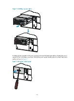
Page 19: ...HP FlexFabric 7900 Switch Series see Appendix B FRUs and compatibility matrixes Figure 14 Installation procedure Figure 15 Removal procedure Remove the power cord Remove the power supply Power off the power supply Installing a power supply 1 Wear an ESD wrist strap and make sure it makes good skin contact and is correctly grounded 2 Unpack the power supply and verify that the power supply model is...

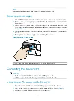
Page 20: ... is installed in the power supply slot remove the blank panel before installing the power supply Thread a flat blade screwdriver through the power supply handle and pull out the blank panel gently as shown in Figure 17 Figure 17 Removing a blank panel 15 ...

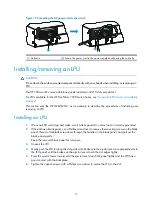
Page 21: ...y bottom with one hand slowly pull the power supply out with the other hand 5 Put away the removed power supply in an antistatic bag for future use Figure 18 Removing the power supply 1 Push the latch to the handle side with the forefinger 2 Pull out the power supply Connecting the power cord IMPORTANT Use the power cord and the C15 connector supplied with the power supply Switch off the input cir...

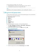
Page 22: ...lling an LPU 1 Wear an ESD wrist strap and make sure it makes good skin contact and is correctly grounded 2 If the slot has a blank panel use a Phillips screwdriver to remove the mounting screws on the blank panel thread a flat blade screwdriver through the handle on the blank panel and pull out the blank panel gently Keep the removed blank panel for future use 3 Unpack the LPU 4 Gently push the L...

Page 23: ...evers at both sides of the LPU outward and pull the LPU along the guide rails until it completely comes out of the switch chassis Do not use excessive force during the operation 4 If no new card is to be installed install the blank panel to prevent dust and ensure good ventilation in the switch Figure 21 Removing an LPU 1 Screw loosening direction 2 Ejector lever direction 3 LPU removing direction...

Page 24: ...19 The grounding cable is securely connected The correct power source is used The power cords are correctly connected ...

Page 25: ...e switch as shown in Figure 22 Figure 22 Connecting the console port to a terminal Connecting the console cable A console cable is an 8 core shielded cable with a crimped RJ 45 connector at one end for connecting to the console port of the switch and a DB 9 female connector at the other end for connecting to the serial port on the console terminal Figure 23 Console cable Main label 1 8 B side B Po...

Page 26: ...st run a terminal emulator program on the console terminal The following are the required terminal settings Bits per second 9 600 Data bits 8 Parity None Stop bits 1 Flow control None Emulation VT100 To set terminal parameters for example on a Windows XP HyperTerminal 1 Select Start All Programs Accessories Communications HyperTerminal The Connection Description dialog box appears 2 Enter the name...

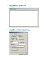
Page 27: ...ng the serial port used by the HyperTerminal connection 4 Set Bits per second to 9600 Data bits to 8 Parity to None Stop bits to 1 and Flow control to None and click OK Figure 26 Setting the serial port parameters 22 ...

Page 28: ... File Properties in the HyperTerminal window Figure 27 HyperTerminal window 6 On the Settings tab set the emulation to VT100 and click OK Figure 28 Setting terminal emulation in Switch Properties dialog box 23 ...

Page 29: ...oling system is operating and you can hear fan rotating and feel air being blown out The LEDs show that the system is operating correctly For more information about LEDs see Appendix C Ports and LEDs Configuring the switch The first time you access the switch you can only log in to the CLI through the console port and no authentication is required To increase system security and enable remote mana...

Page 30: ...ic routes Implement static routing VLANs Divide the LAN into multiple VLANs for data security Configuration example Configuring Telnet service Enter system view Sysname system view Enable the Telnet server Sysname telnet server enable Enter the view of user line VTY 0 Sysname user interface vty 0 Enable password authentication on the user line Sysname ui vty0 authentication mode password Set the p...

Page 31: ...ace brief Display the IP configuration of Layer 3 interfaces display ip interface brief Display brief information about active routes in the routing table display ip routing table Display VLAN settings display vlan Connecting the switch to the network Before you connect the switch to the network verify that all its basic network settings are correct Connecting the switch to the network through an ...

Page 32: ... connector to connect a QSFP module 4 Verify the connection by examining the port LEDs For more information about the LEDs see Appendix C Ports and LEDs Testing connectivity After you plug the switch into the network use the ping or tracert command to test the network connectivity For more information about these commands see HP FlexFabric 7900 Switch Series Command References ...

Page 33: ...and high availability scalability and manageability IRF fabric setup flowchart Figure 31 IRF fabric setup flowchart To set up an IRF fabric Step Description 1 Plan IRF fabric setup Planning IRF fabric size and the installation site Determining the master switch and planning IRF member IDs Planning IRF topology and connections Determining physical IRF ports on the member switches Planning the cabli...

Page 34: ...ows Place all IRF member switches in one rack for centralized high density access Distribute the IRF member switches in different racks to implement the ToR access solution for a data center An IRF fabric is highly scalable After an IRF fabric has been set up you can add new members to the fabric Determining the master switch and planning IRF member IDs An IRF fabric two member roles master and st...

Page 35: ...abric to split as in daisy chain topology Instead the IRF fabric changes to a daisy chain topology without interrupting network services Figure 32 and Figure 33 show the topologies of an IRF fabric made up of three switches The IRF port connections in the two figures are for illustration only and more connection methods are available For information about the physical ports available for IRF conne...

Page 36: ...ibers for long distance connection or use QSFP cables to connect QSFP ports for short distance connection For more information about transceiver modules available for the switch see Appendix B FRUs and compatibility matrixes The following subsections use QSFP cables and QSFP transceiver modules and fibers as examples to describe several IRF connection schemes All these schemes use a ring topology ...

Page 37: ...s an example for connecting 4 top of rack IRF member switches by using QSFP transceiver modules and optical fibers The topology is the same as Figure 35 Figure 36 ToR cabling Configuring basic IRF settings After you install the IRF member switches power on the switches and log in to each IRF member switch see HP FlexFabric 7900 Switch Series Fundamentals Configuration Guide to configure their memb...

Page 38: ...abric and the remote network management station can reach each other 3 Use Telnet Web or SNMP to access the IRF fabric from the network management station See HP FlexFabric 7900 Switch Series Fundamentals Configuration Guide 4 Verify that you can manage all member switches as if they were one node 5 Display the running status of the IRF fabric by using the commands in Table 6 Table 6 Displaying an...

Page 39: ...ate failures by following the guidelines in this chapter contact the local agents or technical support engineers Configuration terminal problems If the configuration environment is set up correctly the configuration terminal displays boot information when the switch is powered on If the setup is incorrect the configuration terminal displays garbled text or does not display anything No terminal dis...

Page 40: ...ly of the same model into the same slot and connect it to the same power input end If the new power supply can operate correctly the old power supply has failed Contact your sales agent or local service engineer to replace the old power supply Fan tray failure The switch provides a fan tray status LED FAN on its rear panel If the FAN LED is red the fan tray is faulty To troubleshoot the fan tray 1...

Page 41: ... interface or the connecting cable might fail To troubleshoot the interface 1 Examine the cable connection of the interface For information about how to correctly connect the cable to an Ethernet interface see Connecting the switch to the network 2 Verify that the cable is in good condition Use the cable to connect two interfaces of the same type that operate correctly If the LEDs of the two inter...

Page 42: ...you will receive email notification of product enhancements new driver versions firmware updates and other product resources Related information Documents To find related documents browse to the Manuals page of the HP Business Support Center website http www hp com support manuals For related documentation navigate to the Networking section and select a networking category For a complete list of a...

Page 43: ...ated by vertical bars from which you select one choice multiple choices or none 1 n The argument or keyword and argument combination before the ampersand sign can be entered 1 to n times A line that starts with a pound sign is comments GUI conventions Convention Description Boldface Window names button names field names and menu items are in bold text For example the New User window appears click ...

Page 44: ... 2 features Represents an access controller a unified wired WLAN module or the switching engine on a unified wired WLAN switch Represents an access point Represents a security product such as a firewall a UTM or a load balancing or security card that is installed in a device Represents a security card such as a firewall card a load balancing card or a NetStream card Port numbering in examples The ...

Page 45: ... power supplies are field replaceable unit FRUs Unless otherwise stated an LPU is referred to as a card in this document For more information about available cards power supplies and fan trays for the HP 7904 switch see Appendix B FRUs and compatibility matrixes Chassis views Figure 37 Front view of the HP 7904 switch 1 LPU slots NOTE The HP 7904 switch comes with filler panels secured to LPU slot...

Page 46: ... Figure 38 shows the rear view of an HP 7904 switch installed with two PSR1800 56A power supplies There are two fan tray slots on the rear panel of the HP 7904 chassis To ensure good heat dissipation you must install two fan trays of the same model Figure 38 shows the rear view of an HP 7904 switch installed with two front to back airflow fan trays JG684A Figure 39 Left side the HP 7904 switch 1 P...

Page 47: ... Depth HP 7904 88 1 mm 3 47 in or 2 RU 440 mm 17 32 in 720 mm 28 35 in If you install the switch in a 19 inch rack by using slide rails reserve the following rack clearance A distance in the range of 590 mm 23 23 in to 980 mm 38 58 in between the front rack post and the rear rack post At least 100 mm 3 94 in between the front rack post and the front door At least 830 mm 32 68 in between the front ...

Page 48: ...tem power consumption The system power consumption of the switch depends on the type and number of the cards and fan trays Minimum system power consumption Static power consumption of all cards Minimum power consumption of all fan trays For example for an HP 7904 switch that has four LSV1QGS12SA1 LPUs and two fan trays the minimum system power consumption is 4 160 2 18 676 W Maximum system power c...

Page 49: ...ecified in ISO 7779 at the bystander position Other specifications Table 14 Other specifications Model System leakage current standard Fusing current Fireproofing standard HP 7904 EN60950 1 GB4943 IEC60950 1 UL60950 1 15 A EN60950 1 GB4943 IEC60950 1 UL60950 1 Cooling system The cooling system of the switch comprises the air vents in the chassis fan tray and built in fans of power supplies To guar...

Page 50: ... vents in the fan tray panel and the power supply panels as shown in Figure 41 Figure 40 Airflow through the switch chassis with the back to front airflow fan tray JG839A 1 Power supply air vents 2 Fan tray air vents 3 Port side air vents Figure 41 Airflow through the switch chassis with the front to back airflow fan tray JG684A 1 Power supply air vents 2 Fan tray air vents 3 Port side air vents 1...

Page 51: ...ower of 1800 W The HP 7904 switch supports 1 1 power redundancy You can install appropriate number of power supplies according to the power supply mode and system power consumption Make sure the total maximum output power of the ordered power supplies is greater than the system power consumption HP recommends that you reserve 20 of the maximum output power Table 16 describes PSR1800 56A power supp...

Page 52: ...Fabric 7904 back power side to front port side airflow Fan Tray 40 x 40 x 56 mm 1 57 x 1 57 x 2 20 in 5 105 CFM 22100 RPM 18 W to 130 W JG684A HP FlexFabric 7904 front port side to back power side airflow Fan Tray 40 x 40 x 56 mm 1 57 x 1 57 x 2 20 in 5 105 CFM 22100 RPM 18 W to 130 W Transceiver modules The HP FlexFabric 7900 switch series supports the following transceiver modules and cables QSF...

Page 53: ...40 40G QSFP QSFP 5m Direct Attach Copper Cable 5 m 16 40 ft Table 20 QSFP to SFP cable specifications Product code Description Cable length Remarks JG329A HP X240 40G QSFP to 4x10G SFP 1m Direct Attach Copper Splitter Cable 1 m 3 28 ft Used for connecting a 40 Gbps QSFP port to four 10 Gbps SFP ports JG330A HP X240 40G QSFP to 4x10G SFP 3m Direct Attach Copper Splitter Cable 3 m 9 84 ft JG331A HP ...

Page 54: ...04 switch has one management Ethernet port You can connect this port to a PC or management station for loading and debugging software or remote management Table 22 Management Ethernet port specifications Item Description Connector type RJ 45 Port transmission rate 10 100 1000 Mbps Transmission medium and max transmission distance 100 m 328 08 ft over category 5 twisted pair cable USB port The HP 7...

Page 55: ...ff The switch is operating as a subordinate switch Flashing green When you execute the flashing beacon switch member id command the ID LED of the specified member switch fast flashes The LED restores to the previous state when you execute the undo flashing beacon command NOTE For more information about the flashing beacon command see HP FlexFabric 7900 Switch Series IRF Command Reference Fan statu...

Page 56: ...Off Off No link is present QSFP port LEDs Each QSFP port has a status LED to show port operating status and activities Table 28 QSFP port LED description LED Status Description QSFP port LED Steady green A transceiver module or cable has been correctly installed The port has a link and is operating at 40 Gbps Flashing green The port is sending or receiving data at 40 Gbps Steady yellow A transceiv...

Page 57: ...tatus Description AC OK Steady green Power input is normal Off No power is being input or the power supply has an input problem DC OK Steady green Power output is normal Steady red The power supply has an output problem Off No power is being output ...

Page 58: ...ecifications 41 I Installation tools 3 Installing the switch in a 19 inch rack 4 Installing removing a fan tray 12 Installing removing a power supply 14 Installing removing an LPU 17 Interface failure 36 IRF fabric setup flowchart 28 L LEDs 50 LPU failure 35 LPUs 46 O Other specifications 44 P Planning IRF fabric setup 29 Ports 49 Power supplies 46 Power supply failure 35 Powering on the switch 24...

Reviews: