485
Displaying and maintaining L2VPN access to
L3VPN or IP backbone
Execute
display
commands in any view and
reset
commands in user view.
Task Command
Display information about L2VE
interfaces or L3VE interfaces.
display interface
[
ve-l2vpn
interface-number
|
ve-l3vpn
interface-number
] [
brief
[
description
|
down
] ]
Clear interface statistics.
reset counters interface
[
ve-l2vpn
interface-number
|
ve-l3vpn
interface-number
]
Improved L2VPN access to L3VPN or IP
backbone configuration examples
Access to MPLS L3VPN through an LDP MPLS L2VPN
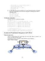
The MPLS L2VPN in this configuration example is a point-to-point MPLS L2VPN that provides
PPP-to-Ethernet interworking.
Network requirements
The backbone is an MPLS L3VPN, which advertises VPN routes through BGP and forwards VPN
packets based on MPLS labels.
CE 1 and CE 2 belong to VPN 1 whose route target is 111:1 and RD is 200:1. CE 1 is connected to
PE 1 through interface Serial 1/1/0, which uses PPP encapsulation. CE 2 is connected to the MPLS
L3VPN through interface GigabitEthernet 1/1/1.
Perform the following configurations to allow communication between CE 1 and CE 2:
•
Set up an LDP PW between PE 1 and PE-agg, so that CE 1 can access the MPLS L3VPN
through MPLS L2VPN.
•
Configure MPLS L2VPN interworking on interface Serial 1/1/0 of PE 1 and the L2VE interface of
PE-agg.
This configuration is required because CE 1 is connected to the MPLS L2VPN through PPP, not
Ethernet or VLAN.
•
Run EBGP between CE 1 and PE-agg and between CE 2 and PE 2 to exchange VPN routing
information.
•
Run MP-IBGP between PE-agg and PE 2 to exchange VPN routing information.
•
Run IS-IS between PE-agg and PE 2 to ensure IP connectivity within the backbone.
•
Run OSPF among PE 1, P, and PE-agg to ensure IP connectivity between the PEs.

