409
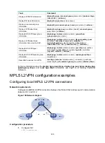
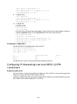
[CE1] interface gigabitethernet 1/1/1
[CE1-GigabitEthernet1/1/1] ip address 100.1.1.1 24
[CE1-GigabitEthernet1/1/1] quit
2.
Configure CE 2.
<CE2> system-view
[CE2] interface gigabitethernet 1/1/1
[CE2-GigabitEthernet1/1/1] ip address 100.1.1.2 24
[CE2-GigabitEthernet1/1/1] quit
3.
Configure PE:
# Enable L2VPN.
<PE> system-view
[PE] l2vpn enable
# Create a cross-connect group named
vpn1
, create a cross-connect named
vpn1
in the group,
and bind GigabitEthernet 1/1/1 and GigabitEthernet 1/1/2 to the cross-connect.
[PE] xconnect-group vpn1
[PE-xcg-vpn1] connection vpn1
[PE-xcg-vpn1-vpn1] ac interface gigabitethernet 1/1/1
[PE-xcg-vpn1-vpn1] ac interface gigabitethernet 1/1/2
[PE-xcg-vpn1-vpn1] quit
Verifying the configuration
# Verify that two AC forwarding entries exist on the PE.
[PE] display l2vpn forwarding ac
Total number of cross-connections: 1
Total number of ACs: 2
AC Xconnect-group Name Link ID
GE1/1/1 vpn1 0
GE1/1/2 vpn1 1
# Verify that CE 1 and CE 2 can ping each other. (Details not shown.)
Configuring IP interworking over local MPLS L2VPN
connections
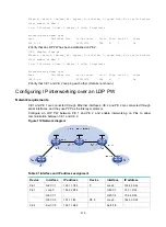
Network requirements
CE 1 and PE are connected through Ethernet interfaces. CE 2 and PE are connected through serial
interfaces, and they use PPP as the link layer protocol.
Configure local MPLS L2VPN connections between the PE and CEs and enable interworking on the
PE to allow communication between CE 1 and CE 2.


