510
•
When the Type field is 2, the Administrator subfield occupies four bytes, the Assigned number
subfield occupies two bytes, and the RD format is
32-bit AS number
:
16-bit user-defined number
,
where the minimum value of the AS number is 65536. For example, 65536:1.
To guarantee global uniqueness for a VPN-IPv4 address, do not set the Administrator subfield to any
private AS number or private IP address.
Route target attribute
MPLS L3VPN uses route target community attributes to control the advertisement of VPN routing
information. A VPN instance on a PE supports the following types of route target attributes:
•
Export target attribute
—A PE sets the export target attribute for VPN-IPv4 routes learned
from directly connected sites before advertising them to other PEs.
•
Import target attribute
—A PE checks the export target attribute of VPN-IPv4 routes received
from other PEs. If the export target attribute matches the import target attribute of a VPN
instance, the PE adds the routes to the routing table of the VPN instance.
Route target attributes define which sites can receive VPN-IPv4 routes, and from which sites a PE
can receive routes.
Like RDs, route target attributes can be one of the following formats:
•
16-bit AS number
:
32-bit user-defined number
. For example, 100:1.
•
32-bit IPv4 address:16-bit user-defined number
. For example, 172.1.1.1:1.
•
32-bit AS number
:
16-bit user-defined number
, where the minimum value of the AS number is
65536. For example, 65536:1.
MCE overview
The Multi-VPN Instance CE (MCE) feature allows you to create multiple VPN instances on a CE. The
VPN instances each have an independent routing table and an address space to achieve service
isolation.
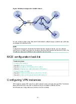
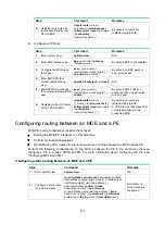
As shown in
, the MCE exchanges private routes with VPN sites and PE 1, and adds the
private routes to the routing tables of corresponding VPN instances.
•
Route exchange between MCE and VPN site
—Create VPN instances VPN 1 and VPN 2 on
the MCE. Bind VLAN-interface 2 to VPN 1, and VLAN-interface 3 to VPN 2. The MCE adds a
received route to the routing table of the VPN instance that is bound to the receiving VLAN
interface.
•
Route exchange between MCE and PE
—The MCE connects to PE 1 through a trunk link that
permits VLAN 2 and VLAN 3. On PE 1, create VPN instances VPN 1 and VPN 2. Bind
VLAN-interface 2 to VPN 1, and VLAN-interface 3 to VPN 2. The MCE and PE add a received
route to the routing table of the VPN instance that is bound to the receiving VLAN interface.

