167
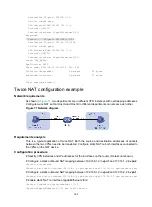
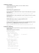
VPN instance/VLAN ID/VLL ID: -/-/-
Protocol: TCP(6)
Inbound interface: GigabitEthernet2/0/2
Responder:
Source IP/port: 10.110.10.3/21
Destination IP/port: 202.38.1.25/53957
DS-Lite tunnel peer: -
VPN instance/VLAN ID/VLL ID: -/-/-
Protocol: TCP(6)
Inbound interface: GigabitEthernet2/0/1
State: TCP_ESTABLISHED
Application: FTP
Start time: 2012-08-16 11:06:07 TTL: 26s
Initiator->Responder: 1 packets 60 bytes
Responder->Initiator: 2 packets 120 bytes
Total sessions found: 5
NAT with DNS mapping configuration example
Network requirements
As shown in
, the internal Web server at 10.110.10.1/16 and FTP server at 10.110.10.2/16
provide services for external user. The company has three public addresses 202.38.1.1 through
202.38.1.3. The DNS server at 202.38.1.4 is on the external network.
Configure NAT so that:
•
The public IP address 202.38.1.2 is used by external users to access the Web and FTP servers.
•
External users can use the public address or domain name of internal servers to access them.
•
Internal users can access the internal servers by using their domain names.
Figure 73 Network diagram
Requirements analysis
To meet the network requirements, perform the following tasks:
•
Configure NAT Server by mapping the public IP addresses and port numbers of the internal
servers to a public address and port numbers so that external users can access the interval
servers.
•
Configure NAT with DNS mapping and ALG so that the public IP address of the internal server
in the payload of the DNS response packet can be translated to the private IP address.


