5.
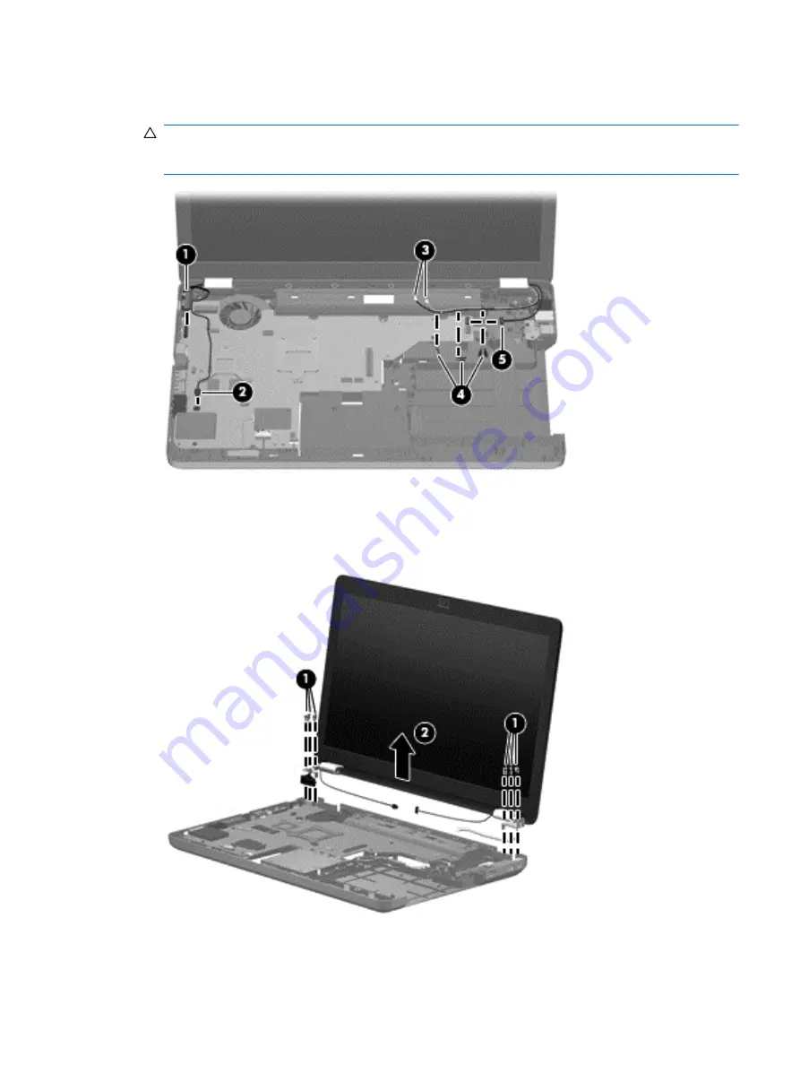
Disconnect the webcam cable
(5)
from the system board and release it from the clips that attach
it to the system board.
CAUTION:
Support the display assembly when removing the display screws in the following
steps. Failure to support the display assembly can result in damage to the assembly and other
components.
6.
Remove the six black Phillips PM2.5×7.0 screws
(1)
that secure the display assembly to the
computer.
7.
Lift the display panel
(2)
straight up to remove it.
Reverse this procedure to install the display assembly.
Component replacement procedures
69
Summary of Contents for G62 Series
Page 4: ...iv Safety warning notice ...
Page 6: ...vi MSG revision history ...
Page 10: ...10 Recycling 114 Battery 114 Display 114 Index 121 x ...
Page 27: ...Computer major components Computer major components 17 ...
Page 34: ......
Page 121: ...Universal Serial Bus Pin Signal 1 5 VDC 2 Data 3 Data 4 Ground Universal Serial Bus 111 ...
Page 130: ...22 Remove the LCD panel 23 Recycle the LCD panel and backlight 120 Chapter 10 Recycling ...
Page 135: ......


