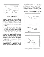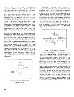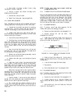
combination is floated free of ground at the power transformer,
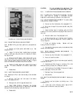
the reference supply serves several purposes: it not only
furnishes the stable voltage for the balance circuit, but also
furnishes all the power requirements for the servo amplifier
with the exception of the Power Transformer T-601 furnishes
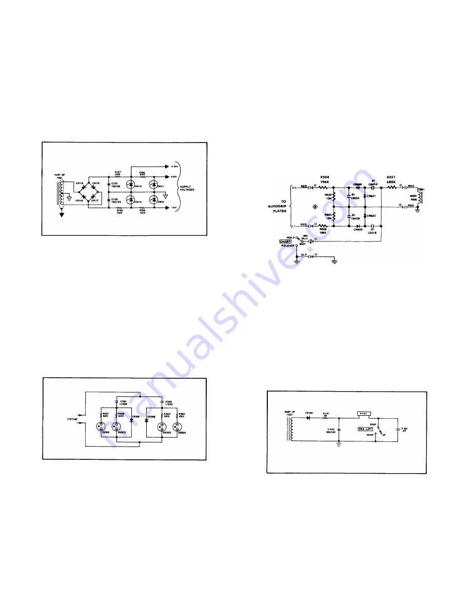
this power from a shielded secondary through rectifying diodes
CR-115 and CR-116 into a peak filter C-125. Two shunt
supplies in series furnish 15 volts for the amplifier's power
stages and 9 volts for the input stages and balance circuit. An
identical but reversed supply furnishes the -9 volts for the zero
circuit.
FIGURE 4-12. POWER AND REFERENCE SUPPLY
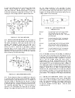
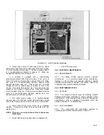
4-22. NEON DRIVER (See Figure 4-13.) The power supply for
the neon bulbs that actuate the photochopper's photo cells is
basically a voltage clamp-in circuit comprised of capacitors
C-301, C-302 and diodes CR-301, CR-302. On alternate half-
cycles, diode CR-301 conducts causing the full power line
voltage to be placed across capacitor C-301. This essentially
doubles the peak value available to ignite the neon bulbs.
Since high brightness neon bulbs are used to efficiently
operate the photo cells, and since the firing voltage of a high
brightness neon bulb prior to aging may vary greatly, this
voltage doubler eliminates the necessity for aged bulbs by
providing a maximum voltage that will always exceed the
fluctuations of the required firing voltage.
FIGURE 4-13. NEON DRIVER
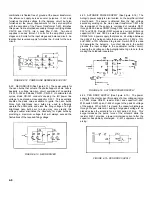
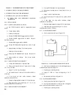
4-23. AUTOGRIP POWER SUPPLY (See Figure 4-14.) The
Autogrip power supply is also located on the amplifier printed
circuit board. The power is obtained from the high voltage
secondary winding on the main power transformer T-601 and
the remainder of the supply is composed of resistors R501
through R505, diodes CR501 through 504, and dual capacitors
C501 and C502. Resistor R501 serves as a current limiter and
capacitor C501 and C502, as well as diodes CR501 through
CR504 form a power supply that places a dc voltage between
the grids of the Autogrip table that is equal to + 380V ± 10%
and -380V ± 10% referenced to ground. Switch S501 is used
to deenergize the Autogrip. A contact closure in the switch
grounds the input voltage to the quadrupler rectifier circuit,
causing the dc voltage on the Autogrip table to go to zero, thus
making the holddown inoperative.
FIGURE 4-14. AUTOGRIP POWER SUPPLY
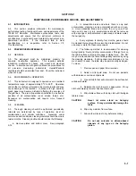
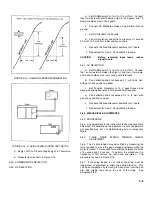
4-24. PEN DROP SUPPLY (See Figure 4-15.) The power
supply for the electric pen lift consists of a low voltage winding
on T-601, diode CR-401, resistor R-401 and capacitor C-402.
With switch S-401 open, C-402 charges to the peak dc voltage
of the supply. When S-401 is closed, the capacitor discharges
through the pen solenoid, causing a large peak voltage to be
placed across the solenoid for a short period of time. This
surge increases the pull-in force of the solenoid while the
resistor R-401 provides a lower maintained current after the
capacitor has partially discharged. C-401 suppresses switch
arcing.
FIGURE 4-15. PEN DROP SUPPLY
4-6
Summary of Contents for HP-7035B
Page 1: ...TECHNICAL MANUAL HEWLETT PACKARD MODEL HP 7035B ...
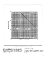
Page 9: ...FIGURE 1 4 DIMENSION DRAWING FIGURE 1 5 ACCESSORIES 1 3 ...
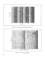
Page 12: ...FIGURE 1 7 TYPICAL FREQUENCY RESPONSE INPUT FILTER FIGURE 1 8 TYPICAL DYNAMIC RESPONSE 1 6 ...
Page 14: ...FIGURE 2 1 WING BRACKET INSTALLATION FIGURE 2 2 STACKED CONFIGURATION 2 2 ...
Page 16: ...FIGURE 3 1 FRONT PANEL CONTROLS 7035B AND 7035B 001 MODELS 3 2 ...
Page 20: ...FIGURE 4 1 BLOCK DIAGRAM FIGURE 4 2 DETAILED BLOCK DIAGRAM 4 2 ...
Page 48: ...TM 11 6625 2850 14 P FIGURE 6 1 EXPLODED VIEW CABINET 6 9 ...
Page 49: ...TM 11 6625 2850 14 P FIGURE 6 2 EXPLODED VIEW CARRIAGE ARM SHEET 1 OF 2 6 10 ...
Page 58: ...FIGURE 7 1 COMPONENT IDENTIFICATION FRAME 7 8 ...
Page 59: ...TM 11 6625 2850 14 P Figure 7 2 Component Identification Circuit Board 7 9 ...
Page 60: ...TM 11 6625 2850 14 P Figure 7 3 Schematic Model 7035B D 07035 92550 7 10 ...
Page 62: ...TM 11 6625 2850 14 P FIGURE 8 1 COMPONENT IDENTIFICATION CIRCUIT BOARD 8 2 ...
Page 66: ...TM 11 6625 2850 14 P FIGURE 8 5 EXPLODED VIEW CARRIAGE ARM 8 6 ...

