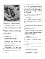
a.
Remove rear hood and platen. See paragraph 5-18.
b.
Snap pen lift solenoid out of its spring holder and
remove holder and X-axis pointer by removing 1 mounting
screw.
c.
Remove wiper assembly mounting screw and install
new wiper, Part No. 5060-4570.
5-27. POTENTIOMETER REPLACEMENT - Y-Axis
5-28. This unit is located in the carriage arm and is part of the
carriage channel. The channel and potentiometer are replaced
as one unit. Replace as follows:
a.
Remove rear hood and platen. See paragraph 5-18.
b.
Remove carriage arm and X-axis slidewire. See
paragraphs 5-20 and 5-24.
c.
Unsolder 3 wires, noting order of leads connected to
slidewire.
d.
Install new slidewire assembly, Part No. 07035-
80750.
5-29. WIPER REPLACEMENT - Y-Axis
5-30. The wiper is made of a soft metal to absorb wear. The
wiper is located on the pen block. New wiper assemblies
should be obtained from the factory and installed as follows:
CAUTION
Damage to the flat mandrel slidewire may
result if other than factory supplied wiper
is used.
a.
Remove rear hood and platen. See paragraph 5-18.
b.
Remove pen scale. See paragraph 5-20.
c.
Remove X-axis potentiometer. See paragraph 5-24.
d.
Remove pen carriage arm. See paragraph 5-22.
e.
Remove wiper assembly from pen block by
unscrewing 1 0-80 screw and nut.
f.
Install new wiper, Part No. 5080-7706.
g.
After reassembling pen carriage, adjust pen carriage.
See paragraph 5-71.
5-31. SERVO MOTOR MAINTENANCE
5-32. The magnetic field strength of the servo motor will
weaken if the rotor is removed from within the magnet. Upon
reassembly, it will be impossible for the motor to return to
specified performance. Therefore, only servo motor
replacement and brush replacement or adjustment are
recommended.
5-33. X-AXIS SERVO MOTOR REPLACEMENT
5-34. To remove:
a.
Remove rear hood and platen. See paragraph 5-18.
b.
Remove 2 No. 4-40 setscrews and slip flywheel off
motor shaft.
c.
Stand recorder on side. Remove bottom cover. See
paragraph 5-18.
d.
Unsolder 2 wires, noting their polarity. Remove 1
capacitor.
e.
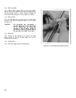
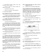
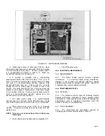
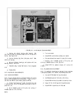
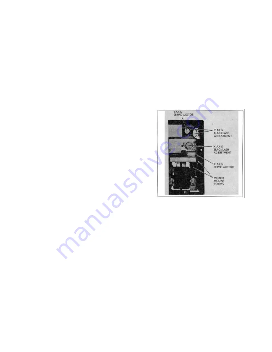
Using Phillips screwdriver, remove 2 screws mounting
motor. See Figure 5-9.
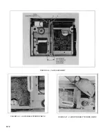
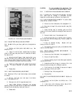
FIGURE 5-9. SERVO MOTOR MAINTENANCE AND
BACKLASH ADJUSTMENTS
f.
Tilt motor so that drive belt can be disengaged.
Remove motor.
g.
Reverse above steps to install.
h.
Adjust X-axis drive belt. See paragraph 5-77.
5-35. Y-AXIS SERVO MOTOR REPLACEMENT
5-36. To remove:
a.
Remove rear hood. See paragraph 5-18.
b.
Move pen carriage to extreme left hand position.
c.
Stand recorder on right side. Remove bottom cover.
See paragraph 5-18.
5-5
Summary of Contents for HP-7035B
Page 1: ...TECHNICAL MANUAL HEWLETT PACKARD MODEL HP 7035B ...
Page 9: ...FIGURE 1 4 DIMENSION DRAWING FIGURE 1 5 ACCESSORIES 1 3 ...
Page 12: ...FIGURE 1 7 TYPICAL FREQUENCY RESPONSE INPUT FILTER FIGURE 1 8 TYPICAL DYNAMIC RESPONSE 1 6 ...
Page 14: ...FIGURE 2 1 WING BRACKET INSTALLATION FIGURE 2 2 STACKED CONFIGURATION 2 2 ...
Page 16: ...FIGURE 3 1 FRONT PANEL CONTROLS 7035B AND 7035B 001 MODELS 3 2 ...
Page 20: ...FIGURE 4 1 BLOCK DIAGRAM FIGURE 4 2 DETAILED BLOCK DIAGRAM 4 2 ...
Page 48: ...TM 11 6625 2850 14 P FIGURE 6 1 EXPLODED VIEW CABINET 6 9 ...
Page 49: ...TM 11 6625 2850 14 P FIGURE 6 2 EXPLODED VIEW CARRIAGE ARM SHEET 1 OF 2 6 10 ...
Page 58: ...FIGURE 7 1 COMPONENT IDENTIFICATION FRAME 7 8 ...
Page 59: ...TM 11 6625 2850 14 P Figure 7 2 Component Identification Circuit Board 7 9 ...
Page 60: ...TM 11 6625 2850 14 P Figure 7 3 Schematic Model 7035B D 07035 92550 7 10 ...
Page 62: ...TM 11 6625 2850 14 P FIGURE 8 1 COMPONENT IDENTIFICATION CIRCUIT BOARD 8 2 ...
Page 66: ...TM 11 6625 2850 14 P FIGURE 8 5 EXPLODED VIEW CARRIAGE ARM 8 6 ...

