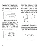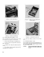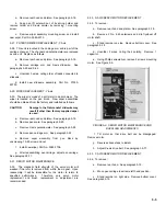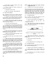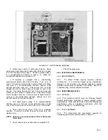
d.
From bottom of recorder, unsolder 2 wires, noting
their polarity. Remove 1 capacitor.
e.
Remove 2 screws and clamps mounting motor.
Withdraw motor from block.
f.
Reverse above steps to install.
g.
Adjust Y-axis drive gears. See paragraph 5-69.
5-37. BRUSH REPLACEMENT
5-38. If it appears the brushes must be replaced, perform the
following steps without removing the motor from the recorder.
a.
Unsolder two motor leads and remove two solder lug
mounting screws. (Note the polarity of the lugs and mark so
that when reassembling a phase reversal will be avoided.)
b.
Unhook brush spring from under tab on each lug.
Pivot brush springs outward and pull brushes out of their holes.
Remove solder lugs and brushes.
c.
Remove two screws retaining end bell.
d.
Carefully pull rear end bell and bearing assembly from
rotor, while holding magnet in place against front end bell.
Make sure rotor remains in place inside motor as rear end bell
is removed. If necessary, push rear end of shaft with a pencil
point or similar object as rear end bell and bearing are
removed.
e.
Blow or brush dust from magnet, rotor, and rear end
bell brush holes. Use an air hose if possible. Be careful not to
lose ball bearing or bearing spacer shims.
f.
Replace rear end bell and bearing assembly. Secure
with two long screws removed earlier.
g.
Replace two solder lugs in end bell slots and secure
with screws.
h.
Install each brush in brush hole making certain that
arc on bottom of brush matches curvature of commutator.
Pigtail leads should rise straight up out of brush hole until
brush springs have been installed. Use a pencil point to adjust
pigtail and to push brush all the way down into brush hole.
i.
Swing brush springs back to their original position,
engaging slots on top of brushes and hook rear end of each
spring under tab on terminal lug. Fold pigtails into top of spring
slot so they are below surface of end bell. Solder motor wires
to the correct lugs.
j.
Operate recorder. If pen drives into stops instead of
seeking null, motor polarity has been inadvertently reversed.
Reconnect motor wires to opposite terminal lugs.
k.
Run recorder through complete performance check.
If brushes are not seating well, apply a 0.3 Hz sine wave to
recorder, adjust to 85% of full scale travel, and let recorder run
for an hour.
NOTE: If either servo motor was removed, install per
paragraph 5-34 or 5-36.
5-39.
CORRECTION OF STICKING MOTOR BRUSHES
5-40. The most common cause of a sticking motor brush is an
interference between the motor body and the brush lead wire,
preventing the brush from moving downward. By carefully
repositioning the lead, the brush can be freed. Other possible
causes of a sticking brush are burrs in its holes or an
accumulation of foreign matter. I either of these is the cause,
the motor will have to be removed and cleaned or replaced.
5-41. Y-AXIS RESTRINGING
5-42. To restring, using Y-axis cable assembly, Part No.
07035-61420, perform the following procedure:
a.
Remove rear hood and platen. See paragraph 5-18.
b.
Remove carriage arm and pen block. See
paragraphs 5-20 and 5-22.
c.
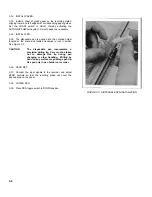
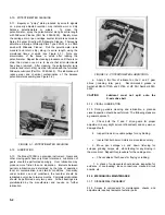
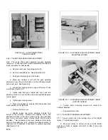
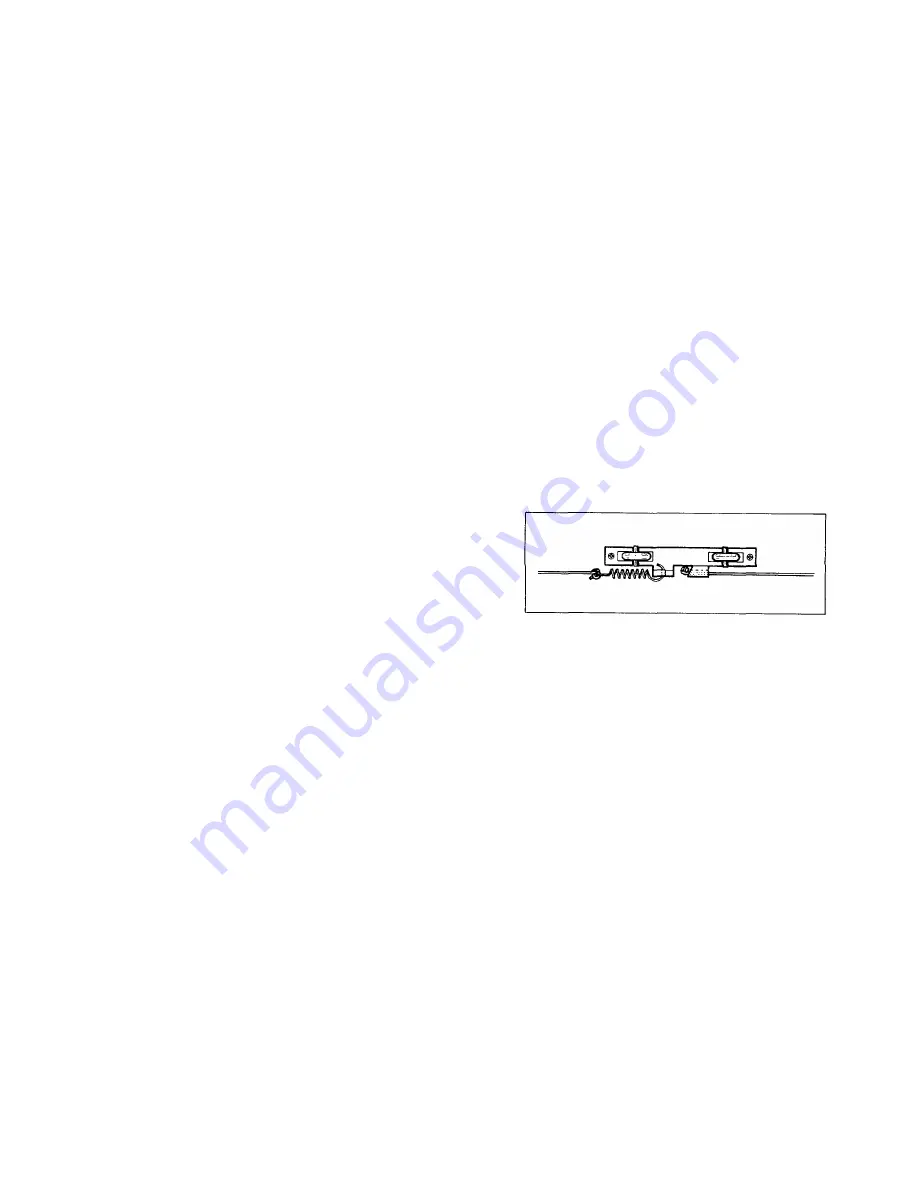
Attach free end of tension spring to the hook on pen
block. Insert knotted end of new nylon cord assembly in
groove of pen block. See Figure 5-10.
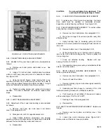
FIGURE 5-10. NYLON CABLE (ATTACHMENT TO PEN
BLOCK)
d.
Slide pen block into carriage arm. Ensure cable is
between pen block and slidewire. Care should be taken not to
damage wiper.
e.
Loop cord around upper and lower pulleys.
f.
Reassemble.
g.
Make cable tension check. See paragraph 5-65.
5-43. X-AXIS RESTRINGING
5-44. To restring, using X-axis cable assembly, Part No. 5080-
3627, perform the following procedure:
a.
Remove rear hood and platen. See paragraph 5-18.
b.
Position carriage arm at convenient location and
fasten securely with tape to prevent movement. Remove old
cable.
c.
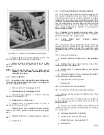
Make small loop in one end of cable and clinch with
cable crimp. See Figure 5-11.
5-6
Summary of Contents for HP-7035B
Page 1: ...TECHNICAL MANUAL HEWLETT PACKARD MODEL HP 7035B ...
Page 9: ...FIGURE 1 4 DIMENSION DRAWING FIGURE 1 5 ACCESSORIES 1 3 ...
Page 12: ...FIGURE 1 7 TYPICAL FREQUENCY RESPONSE INPUT FILTER FIGURE 1 8 TYPICAL DYNAMIC RESPONSE 1 6 ...
Page 14: ...FIGURE 2 1 WING BRACKET INSTALLATION FIGURE 2 2 STACKED CONFIGURATION 2 2 ...
Page 16: ...FIGURE 3 1 FRONT PANEL CONTROLS 7035B AND 7035B 001 MODELS 3 2 ...
Page 20: ...FIGURE 4 1 BLOCK DIAGRAM FIGURE 4 2 DETAILED BLOCK DIAGRAM 4 2 ...
Page 48: ...TM 11 6625 2850 14 P FIGURE 6 1 EXPLODED VIEW CABINET 6 9 ...
Page 49: ...TM 11 6625 2850 14 P FIGURE 6 2 EXPLODED VIEW CARRIAGE ARM SHEET 1 OF 2 6 10 ...
Page 58: ...FIGURE 7 1 COMPONENT IDENTIFICATION FRAME 7 8 ...
Page 59: ...TM 11 6625 2850 14 P Figure 7 2 Component Identification Circuit Board 7 9 ...
Page 60: ...TM 11 6625 2850 14 P Figure 7 3 Schematic Model 7035B D 07035 92550 7 10 ...
Page 62: ...TM 11 6625 2850 14 P FIGURE 8 1 COMPONENT IDENTIFICATION CIRCUIT BOARD 8 2 ...
Page 66: ...TM 11 6625 2850 14 P FIGURE 8 5 EXPLODED VIEW CARRIAGE ARM 8 6 ...

