LIST OF ILLUSTRATIONS
Figure
Page
1-1
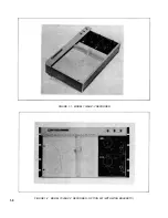
Model 7035B X-Y Recorder ..........................
1-0
1-2
Model 7035B X-Y Recorder- Opt. 001
(With Wing Brackets) .................................
1-0
1-3
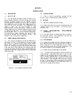
Instrument Identification ..............................
1-1
1-4
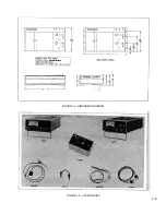
Dimension Drawing .....................................
1-3
1-5
Accessories ................................................
1-3
1-6
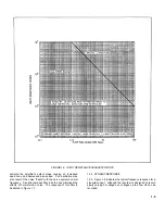
Input Resistance Characteristics ..................
1-5
1-7
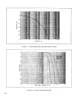
Typical Frequency Response
(Input Filter) ..............................................
1-6
1-8
Typical Dynamic Response .........................
1-6
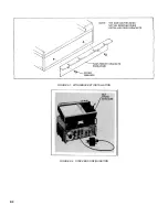
2-1
Wing Bracket Installation .............................
2-2
2-2
Stacked Configuration .................................
2-2
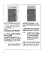
3-1
Front Panel Controls (7035B and
7035B-001) Models ...................................
3-2
3-2
Rear Panel ..................................................
3-3
3-3
Disposable Pen Installation .........................
3-4
4-1
Block Diagram .............................................
4-2
4-2
Detailed Block Diagram................................
4-2
4-3
Range Selector ...........................................
4-3
4-4
Input Filter ..................................................
4-3
4-5
Zero Circuit .................................................
4-3
4-6
Slidewire and Damping Circuit ......................
4-3
4-7
Photochopper and Balance Circuit................
4-4
4-8
Differential Amplifier .....................................
4-4
4-9
Voltage Amplifier .........................................
4-5
4-10
Amplifier/Demodulator .................................
4-5
4-11
Motor Control and Demodulator ...................
4-5
4-12
Power and Reference Supply ......................
4-6
4-13
Neon Driver. ...............................................
4-6
4-14
Autogrip Power Supply ................................
4-6
4-15
Pen Drop Supply .........................................
4-6
5-1
Potentiometer Cleaning ...............................
5-2
5-2
Potentiometer Lubrication.............................
5-2
5-3
Tilting Out Entire Circuit Board
Assembly ...................................................
5-3
5-4
Side Panel Removal ....................................
5-3
Figure
Page
5-5
Pen Scale Removal .....................................
5-4
5-6
Carriage Arm Removal ................................
5-4
5-7
Removal of X-Axis Rebalance
Potentiometer ...........................................
5-4
5-8
X-Axis Wiper Protection ...............................
5-4
5-9
Servo Motor Maintenance and
Backlash Adjustments ...............................
5-5
5-10
Nylon Cable (Attachment to Pen
Block) ........................................................
5-6
5-11
Restringing Diagram ....................................
5-7
5-12
Y-Axis Slewing Speed Test Setup.................
5-8
5-13
Slewing Speed Determination.......................
5-9
5-14
X-Axis Slewing Speed Test Setup.................
5-9
5-15
Y-Axis Drive String Tension Check ............... 5-10
5-16
Y-Axis Backlash Adjustment
(Gear Adjusting Screw) ............................. 5-10
5-17
Y-Axis Backlash Adjustment
(Gear Locking Screw) ................................ 5-10
5-18
Y-Axis Pen Carriage Adjustment................... 5-11
5-19
Y-Axis Alignment ......................................... 5-12
5-20
X-Axis Cable Tension Check ....................... 5-12
5-21
X-Axis Drive Belt Tension Check ................. 5-12
5-22
Drive Train Adjustments .............................. 5-13
5-23
X-Axis Gear Train Bearings ......................... 5-14
5-24
Circuit Board Adjustment ............................. 5-15
6-1
Exploded View - Cabinet .............................
6-9
6-2
Exploded View - Carriage Arm
(Sheet 1 of 2) ............................................ 6-10
6-2
Exploded View - Carriage Arm
(Sheet 2 of 2) ............................................ 6-11
7-1
Component Identification -
Frame ....................................................... 7- 8
7-2
Component Identification -
Circuit Board .............................................
7-9
7-3
Schematic Model 7035B
(D-07035-92550) ....................................... 7-10
8-1
Component Identification - Circuit .................
Board ........................................................
8-2
8-2
Control Panels - Model S 0735B
and 7035B-001 .........................................
8-3
8-3
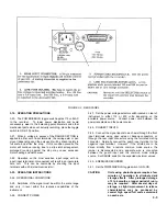
IEC Power Connection ................................
8-4
8-4
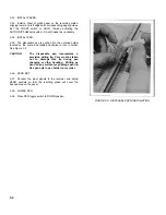
Filling Ink Pen .............................................
8-4
8-5
Exploded View - Carriage Arm .....................
8-6
LIST OF TABLES
Table
Page
1-1
Model 7035B Specifications .........................
1-2
1-2
Accessory Supplies .....................................
1-4
5-1
Recommended Test Equipment ...................
5-8
6-1
Parts List ....................................................
6-2
6-2
Miscellaneous Parts ....................................
6-6
Table
Page
6-3
Recommended One Year
Isolated Spare Parts List ...........................
6-7
6-4
Manufacturer's Code List .............................
6-8
7-1
7035B Troubleshooting Index ......................
7-2
v
Summary of Contents for HP-7035B
Page 1: ...TECHNICAL MANUAL HEWLETT PACKARD MODEL HP 7035B ...
Page 9: ...FIGURE 1 4 DIMENSION DRAWING FIGURE 1 5 ACCESSORIES 1 3 ...
Page 12: ...FIGURE 1 7 TYPICAL FREQUENCY RESPONSE INPUT FILTER FIGURE 1 8 TYPICAL DYNAMIC RESPONSE 1 6 ...
Page 14: ...FIGURE 2 1 WING BRACKET INSTALLATION FIGURE 2 2 STACKED CONFIGURATION 2 2 ...
Page 16: ...FIGURE 3 1 FRONT PANEL CONTROLS 7035B AND 7035B 001 MODELS 3 2 ...
Page 20: ...FIGURE 4 1 BLOCK DIAGRAM FIGURE 4 2 DETAILED BLOCK DIAGRAM 4 2 ...
Page 48: ...TM 11 6625 2850 14 P FIGURE 6 1 EXPLODED VIEW CABINET 6 9 ...
Page 49: ...TM 11 6625 2850 14 P FIGURE 6 2 EXPLODED VIEW CARRIAGE ARM SHEET 1 OF 2 6 10 ...
Page 58: ...FIGURE 7 1 COMPONENT IDENTIFICATION FRAME 7 8 ...
Page 59: ...TM 11 6625 2850 14 P Figure 7 2 Component Identification Circuit Board 7 9 ...
Page 60: ...TM 11 6625 2850 14 P Figure 7 3 Schematic Model 7035B D 07035 92550 7 10 ...
Page 62: ...TM 11 6625 2850 14 P FIGURE 8 1 COMPONENT IDENTIFICATION CIRCUIT BOARD 8 2 ...
Page 66: ...TM 11 6625 2850 14 P FIGURE 8 5 EXPLODED VIEW CARRIAGE ARM 8 6 ...

