SECTION VII
TROUBLESHOOTING
7-1. INTRODUCTION
7-2. CONTENT
7-3. This section contains instructions for troubleshooting the
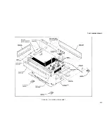
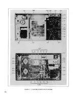
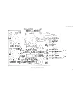
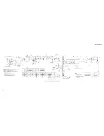
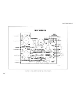
Model 7035B. Component location photographs, schematics,
and a troubleshooting index are supplied to aid in
troubleshooting.
7-4. TROUBLESHOOTING
7-5. REQUIREMENTS
7-6. Troubleshooting should be performed in a logical manner.
The concept of bracketing should be established, such as
determining which circuits or sections are not operating or are
operating abnormally. This is generally the fastest method to
locate trouble in a closed loop circuit. When troubleshooting
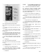
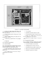
utilize the photographs and schematics presented in this
section, Figures 7-1 through 7-3.
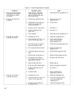
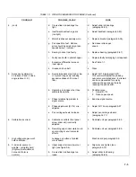
7-7. TROUBLESHOOTING INDEX
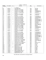
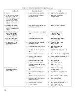
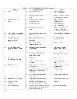
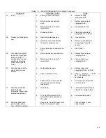
7-8. The troubleshooting index, Table 7-1, lists other possible
malfunctions, suspected causes, and remedies. Use
component location photographs and schematics for backup
when searching out a problem area.
7-1
Summary of Contents for HP-7035B
Page 1: ...TECHNICAL MANUAL HEWLETT PACKARD MODEL HP 7035B ...
Page 9: ...FIGURE 1 4 DIMENSION DRAWING FIGURE 1 5 ACCESSORIES 1 3 ...
Page 12: ...FIGURE 1 7 TYPICAL FREQUENCY RESPONSE INPUT FILTER FIGURE 1 8 TYPICAL DYNAMIC RESPONSE 1 6 ...
Page 14: ...FIGURE 2 1 WING BRACKET INSTALLATION FIGURE 2 2 STACKED CONFIGURATION 2 2 ...
Page 16: ...FIGURE 3 1 FRONT PANEL CONTROLS 7035B AND 7035B 001 MODELS 3 2 ...
Page 20: ...FIGURE 4 1 BLOCK DIAGRAM FIGURE 4 2 DETAILED BLOCK DIAGRAM 4 2 ...
Page 48: ...TM 11 6625 2850 14 P FIGURE 6 1 EXPLODED VIEW CABINET 6 9 ...
Page 49: ...TM 11 6625 2850 14 P FIGURE 6 2 EXPLODED VIEW CARRIAGE ARM SHEET 1 OF 2 6 10 ...
Page 58: ...FIGURE 7 1 COMPONENT IDENTIFICATION FRAME 7 8 ...
Page 59: ...TM 11 6625 2850 14 P Figure 7 2 Component Identification Circuit Board 7 9 ...
Page 60: ...TM 11 6625 2850 14 P Figure 7 3 Schematic Model 7035B D 07035 92550 7 10 ...
Page 62: ...TM 11 6625 2850 14 P FIGURE 8 1 COMPONENT IDENTIFICATION CIRCUIT BOARD 8 2 ...
Page 66: ...TM 11 6625 2850 14 P FIGURE 8 5 EXPLODED VIEW CARRIAGE ARM 8 6 ...

