background image

Installation

Guide

HP

70909A

and

HP

70910A

RF

Section

ABCDE

HP

P

art

No

.

70909-90002

Printed

in

US

A

April

1993

Summary of Contents for HP 70909A

Page 1: ...Installation Guide HP 70909A and HP 70910A RF Section ABCDE HP Part No 70909 90002 Printed in USA April 1993 ...

Page 2: ...this material Restricted Rights Legend Use duplication or disclosure by the U S Government is subject to restrictions as set forth in subparagraph c 1 ii of the Rights in Technical Data and Computer Software clause at DFARS 252 227 7013 for DOD agencies and subparagraphs c 1 and c 2 of the Commercial Computer Software Restricted Rights clause at FAR 52 227 19 for other agencies c Copyright Hewlett...

Page 3: ...another country Hewlett Packard warrants that its software and rmware designated by Hewlett Packard for use with an instrument will execute its programming instructions when properly installed on that instrument Hewlett Packard does not warrant that the operation of the instrument or software or rmware will be uninterrupted or error free Limitation of Warranty The foregoing warranty shall not appl...

Page 4: ... not correctly performed or adhered to could result in damage to or destruction of the instrument Do not proceed beyond a caution sign until the indicated conditions are fully understood and met Warning The warning sign denotes a hazard It calls attention to a procedure which if not correctly performed or adhered to could result in injury or loss of life Do not proceed beyond a warning sign until ...

Page 5: ...sult in personal injury Warning There are many points in the instrument which can if contacted cause personal injury Be extremely careful Any adjustments or service procedures that require operation of the instrument with protective covers removed should be performed only by trained service personnel Caution Before this instrument is switched on make sure its primary power circuitry has been adapt...

Page 6: ...Installation at a Glance vi ...

Page 7: ... driver A nonconductive stylus such as a toothpick or similar object for setting address switches Antistatic precautions Electrical components are easily damaged by small amounts of static electricity If possible work at a static safe work station Installation overview The installation procedure for the HP 70909A or HP 70910A RF section is straightforward The following major steps are included Ste...

Page 8: ...installation of additional and alternate modules that can be used in this system refer to that module s installation guide Chapter 1 of this book presents step by step instructions that are required for proper installation of either an HP 70909A or HP 70910A RF section in an HP 70000 Series modular spectrum analyzer system Chapter 2 of this book presents information to help identify and resolve pr...

Page 9: ... system s ac line power 1 9 Step 9 Check proper operation of your new RF section 1 10 2 If you have problems with installation If the system s power on self test fails 2 2 If your RF section is powered on but not responding correctly 2 4 If the STATUS ERR indicator LED on your new RF section is ashing 2 5 If more than one module s error indicator is ashing 2 6 If hardware errors messages occur 2 7...

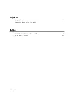
Page 10: ...Figures 2 1 Line Voltage Selector 2 2 2 2 Line Fuse Removal and Replacement 2 2 Tables 2 1 Hewlett Packard Sales and Service O ces 2 10 2 2 Packaging and Contents 2 12 Contents 2 ...

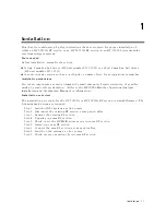
Page 11: ...f static electricity If possible work at a static safe work station Refer to the HP 70000 Modular Spectrum Analyzer Installation and Veri cation Manual for information Installation overview The installation procedure for the HP 70909A or HP 70910A RF section is straightforward The following major steps are included Step 1 Switch o the system s ac line power Step 2 Disconnect the existing RF sectio...

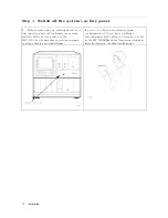
Page 12: ...tem switch o the ac line power to the HP 70000 Series modular spectrum analyzer system s display and mainframe If you do not have a standard system con guration or if you have problems determining which cables to disconnect refer to the HP 70000 Modular Spectrum Analyzer Installation and Veri cation Manual 1 2 Installation ...

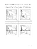
Page 13: ...isting RF section s 21 4 MHz OUT connector 2 Disconnect the SMB cable from the existing RF section s 300 MHz IN connector 3 Disconnect the SMB cable from the existing RF section s TUNE SPAN connector 4 Disconnect the SMA exible cable from the existing RF section s 1ST LO IN connector Installation 1 3 ...

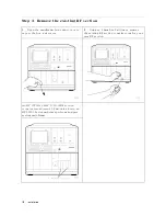
Page 14: ...xpose the hex lock screw 2 Using an 8 mm hex ball driver remove the existing RF section to make room for your new RF section An HP 70909A or HP 70910A RF section occupies two adjacent 1 8 module slots in an HP 70000 Series modular spectrum analyzer system mainframe 1 4 Installation ...

Page 15: ...tainer and inspect it thoroughly to ensure that it was not damaged during shipment 2 Verify that all parts and materials were included in the shipping container 1 HP 70909A RF section or HP 70910A RF section 2 HP 70909A and HP 70910A Installation Guide 3 HP 71209A Quick Start Guide 4 Package of cables Installation 1 5 ...

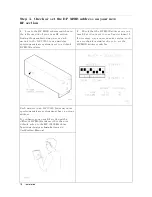
Page 16: ...s 2 Check that the HP MSIB address on your new RF section is set to row 6 and column 18 If necessary use a nonconductive stylus such as a toothpick or similar object to set the HP MSIB address switches Each module in an HP 70000 Series modular spectrum analyzer system must have a unique address To con gure your new RF section with a di erent HP MSIB address other than its default refer to the HP 7...

Page 17: ...on into the mainframe 2 Press against your new RF section s front panel while tightening the hex nut latch with an 8 mm hex ball driver This locks your new RF section into position 3 Close the mainframe front panel door to cover the hex lock screw Installation 1 7 ...

Page 18: ... IN connector 2 Connect an SMB cable from the LO section s 300 MHz OUT connector to your new RF section s 300 MHz IN connector 3 Connect an SMB cable from the LO section s TUNE SPAN connector to your new RF section s TUNE SPAN connector 4 Connect an SMA exible cable from the LO section s LO OUT connector to your new RF section s 1ST LO IN connector 1 8 Installation ...

Page 19: ...ower cords to the rear of the HP 70000 Series modular spectrum analyzer system display and mainframe Then connect the other ends of the ac power cords to the line voltage Caution Before turning this instrument on make sure the line voltage selector is set to the voltage of the ac power source 115 V position for 90 to 132 V ac line input voltages at 50 60 or 400 Hz 230 V position for 198 to 264 V a...

Page 20: ...h on momentarily and then turn o again 2 If the power on self test passes the MEASURE LED on the LO module starts blinking on and o being triggered by the system sweep and the ACT LED on each active module s front panel is turned on If you have problems with installation refer to Chapter 2 There are no veri cation tests or speci cations for the RF section by itself it must be tested in a system Fo...

Page 21: ...tion or explanation to help provide more insight into their cause A possible cause for the symptom and a checklist of possible solutions are then presented Use this checklist as an aid to correct the problem If a problem cannot be resolved you can return the equipment to Hewlett Packard for servicing Instructions for returning your RF section to Hewlett Packard for servicing are provided in Before...

Page 22: ...e HP 70000 Series modular spectrum analyzer system display and mainframe are plugged into the proper ac line voltage Check that the line socket has ac line voltage Check that the line voltage selector switch is set to the correct voltage for the ac line voltage being used The line voltage selector switch is located on the left side of the HP 70004A display or on the bottom of the HP 70001A mainfra...

Page 23: ...If necessary obtain HP service Refer to If you require additional technical resources If you have problems with installation 2 3 ...

Page 24: ...s problem Perform the checks in the procedure If the system s power on self test fails Check that other equipment cables and connectors are connected and operating correctly Check the HP 70000 Series modular spectrum analyzer system display for error messages If necessary obtain HP service Refer to If you require additional technical resources 2 4 If you have problems with installation ...

Page 25: ...ing steps 1 Switch o the system s ac line power 2 Disconnect the RF section s rear panel cables 3 Remove the RF section from the system 4 Switch on the system s ac line power and check that no error LEDs are ashing on the other system modules 5 If all other modules are working correctly use the steps outlined in Chapter 1 to reinstall the RF section Check that the HP MSIB address is set correctly ...

Page 26: ... HP MSIB address is set correctly Refer to Step 5 Check or set the HP MSIB address on your new RF section in Chapter 1 If two separate modules are set to the same HP MSIB address this problem will occur Remove all modules and reinstall them one at a time until a module that causes the ERR LED to ash is found Turn the power on each time after a module is removed to determine if the problem has been...

Page 27: ...leveled To solve this problem 1 Check the rear panel 1ST LO IN connection 2 Refer to the HP 70909A and HP 70910A Service Guide for troubleshooting information 3 If necessary obtain HP service Refer to If you require additional technical resources 7003 2nd LO unlocked This hardware error occurs when the signal of the 2nd local oscillator s phase locked loop circuitry is not phase locked to the 300 ...

Page 28: ...itional technical resources 7078 Tune Span error This hardware error occurs when the Tune Span voltage on the A19 Power Supply Driver assembly is low To solve this problem 1 Check the rear panel TUNE SPAN connection 2 Refer to the HP 70909A and HP 70910A Service Guide for troubleshooting information 3 If necessary obtain HP service Refer to If you require additional technical resources 7079 EEPROM...

Page 29: ...ide Hewlett Packard o ers several maintenance plans to service your HP 70909A or HP 70910A RF section after warranty expiration your Hewlett Packard sales and service o ce can provide full details If your HP 70909A or HP 70910A RF section are covered by a separate maintenance agreement please be familiar with its terms before calling Hewlett Packard for service If you want to service the HP 70909A...

Page 30: ...tt Packard GmbH Kirkland Quebec H9J 2X8 Colorado Berner Strasse 117 Canada Hewlett Packard Co 6000 Frankfurt 56 514 697 4232 24 Inverness Place East West Germany Englewood CO 80112 49 69 500006 0 303 649 5000 Japan Great Britain Yokogawa Hewlett Packard Ltd Georgia Hewlett Packard Ltd 1 27 15 Yabe Sagamihara Hewlett Packard Co Eskdale Road Winnersh Triangle Kanagawa 229 Japan 2000 South Park Place...

Page 31: ...quipment damage by generating static electricity or by lodging in fan motors 2 Place the RF section in its original packaging materials see Table 2 2 If the original packaging materials are not available you can contact a Hewlett Packard sales and service o ce to obtain information on packaging materials or you may use an alternative packing material referred to as bubble pack One of the companies...

Page 32: ...d Contents Item Description HP Part Number Qty 1 Carton outer 9211 5118 1 2 Carton inner 9211 5119 1 3 Carton sliders 5180 2369 2 4 Foam inserts 4208 0493 2 5 Foam pads 5180 2370 2 2 12 If you have problems with installation ...

Reviews: